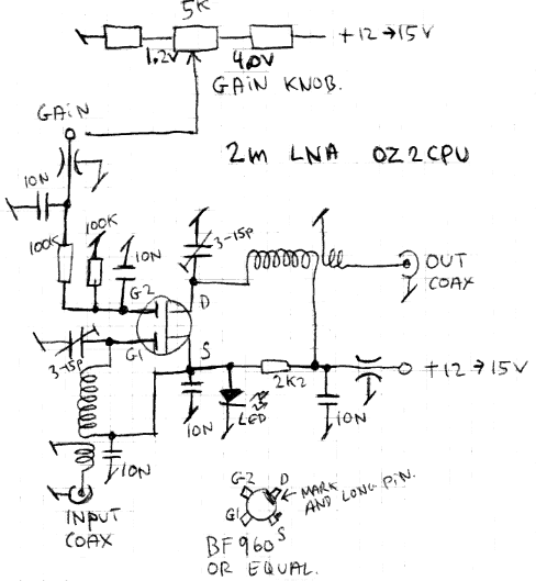
2m Dual Gate FET Low Noise Amplifier.
My good old FT-290 2m SSB and FM radio, had about 1uV sensitivity before installing this amp.Now it is 150nV just like the best radios I have tested. Stations I could hear with noise, are now loud and clear !!

Here is the schematic. Sorry it is just my own handdrawn lab note.
The gain controll voltage can be adjusted from 1.2 to 4.0 Volt
Then the Gain vil change from -20 to +20db

The box is an old RF video modulator, I have made a "wall" with a hole for the dual gate FET,
So that Gate1 and Gate2 is inside one part, Drain and Source is inside the other part of the box.
The two coils may not be allowed to transfer any signal to each other. else you have a nice oscillator and not an amplifier.

Here the LNA-box mounted inside my FT-290, the useless battery box is removed.

A track is cutted before the first amp inside the FT-290, then the input and output coax is mounted, nice and easy..
The best few hours I have ever spend improving this rig !!

The memory switch was removed and a 5K potentiometer installed, now the Gain Knob.
I have placed marks at every 10dB at the front, So I can see what happens when I adjust,
Here the knob is placed at +15dB gain.
Made in April 2002, OZ2CPU, www.webx.dk