 www.webx.dk Start page
 OZ2CPU Radioamateur mainpage
 Homemade electronics Stuff old and new
 Raspberry PI highend hifi music player streamer
www.webx.dk Start page
OZ2CPU Radioamateur mainpage
Homemade electronics Stuff old and new
Raspberry PI highend hifi music player streamer
Foreword:
I tried several readymade music streamers, none of them worked perfectly out of the box, random crashes, lack of features, poor audio quality
So i desided to construct my own using a raspberry PI and external high definition DAC
I started with a PI1 so that is why my sound card dont fit my new PI3, dont matter since I want the RCA connectors out the back
so wires for the 3 seial lines and power must be added, no big deal. I2S clock and data go from 1.4 MHz to 14 MHz, depending on bits and sample rate.
so twist the signals with a nearby ground, this way the fast signals are matched.
I have been testing this for 2 years and found it perfectly stable and fully featured after the last firmware upgrade, so now it was time to make a nice case for it.
So this page simply explain a bit about my case construction.
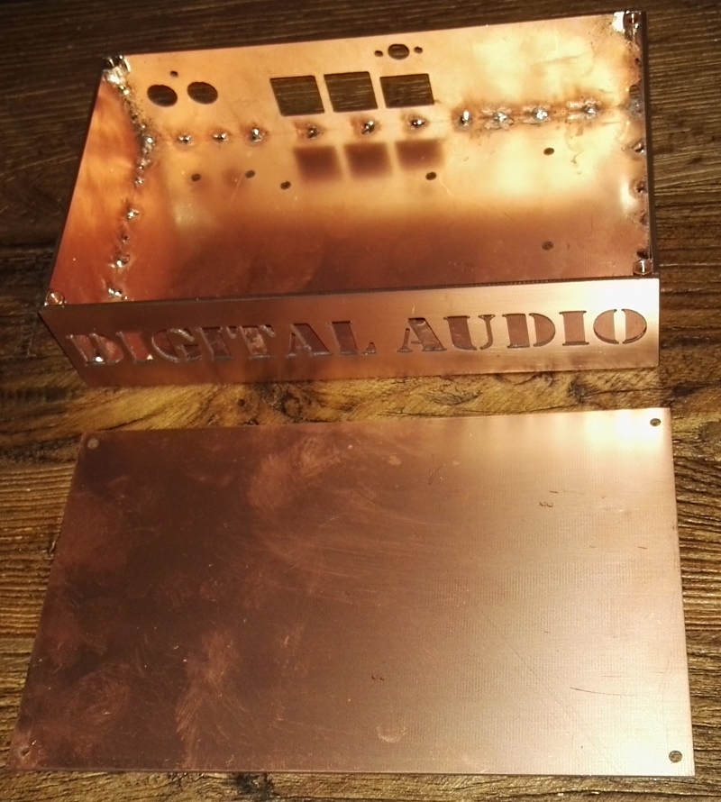
case and the lid, after soldering it all together
size : 100mm deep, 170mm wide, 40mm height
back after clean now ready for paint
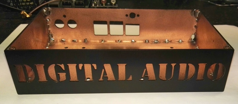
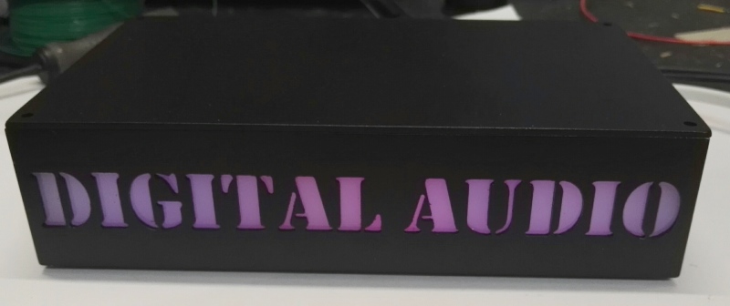
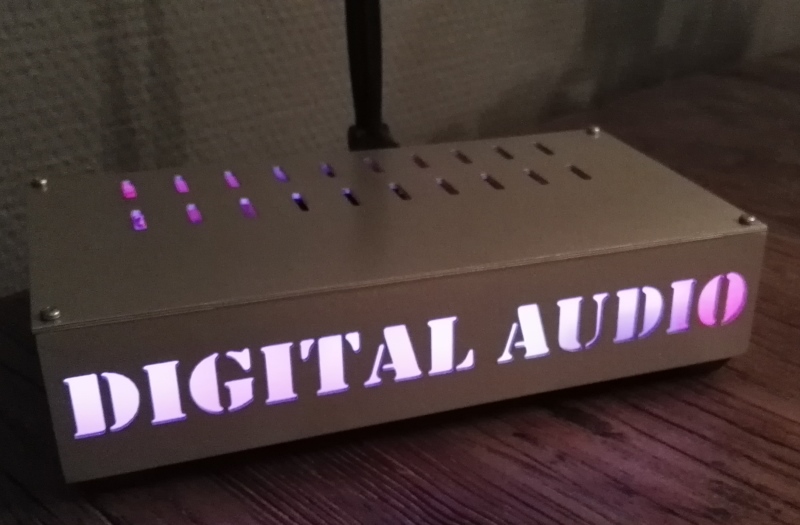
painted front
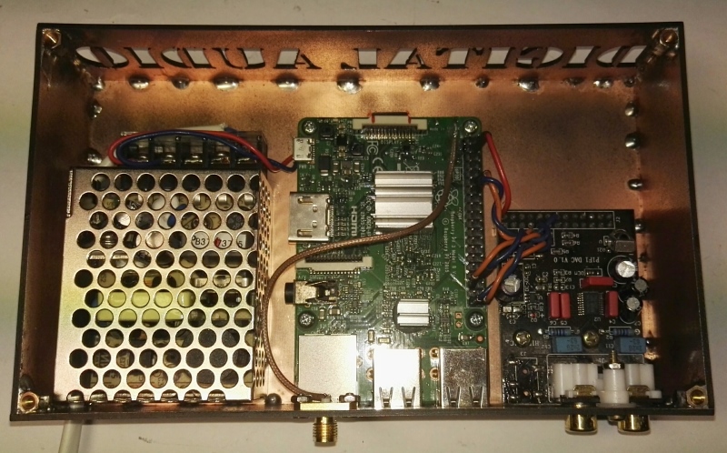
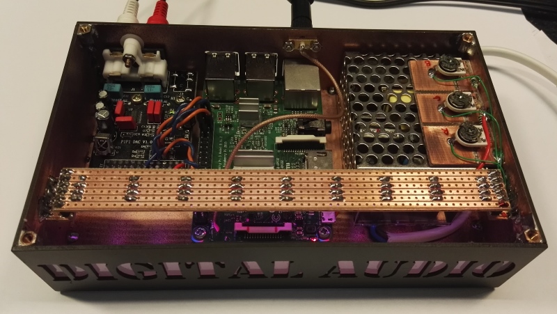
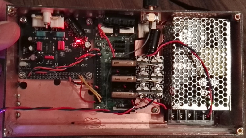
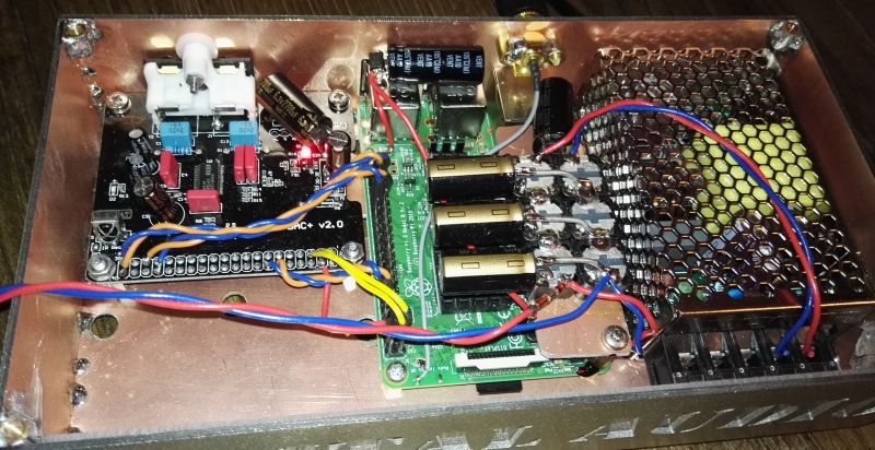
mount all important parts, test it stil play, the PI3 tiny PCB antenna is removed and coax cable added,
SMA connector for antenna on the back, now the wifi got full range due to much better and bigger antenna.
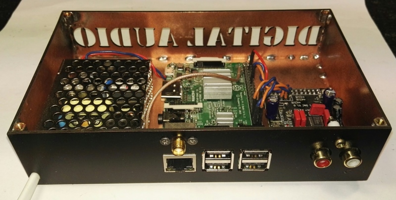
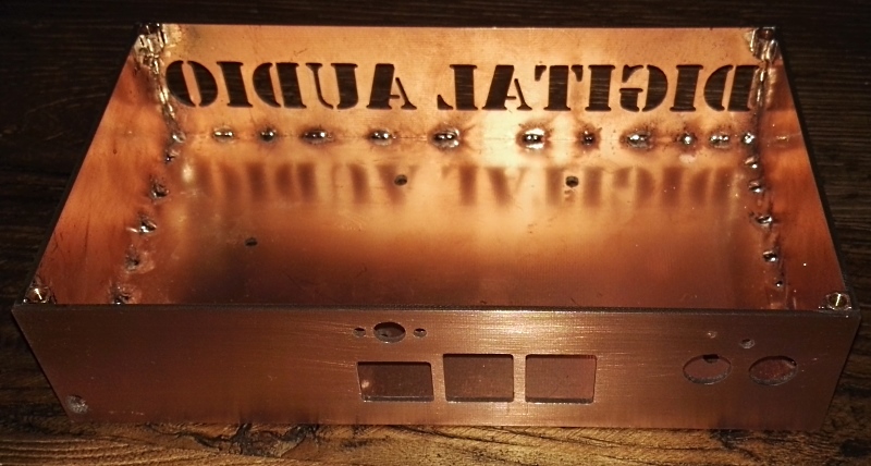
back connectors fit all perfectly, thanks to a good carefull measurement and design in coreldraw
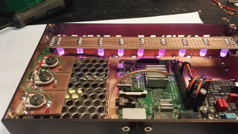
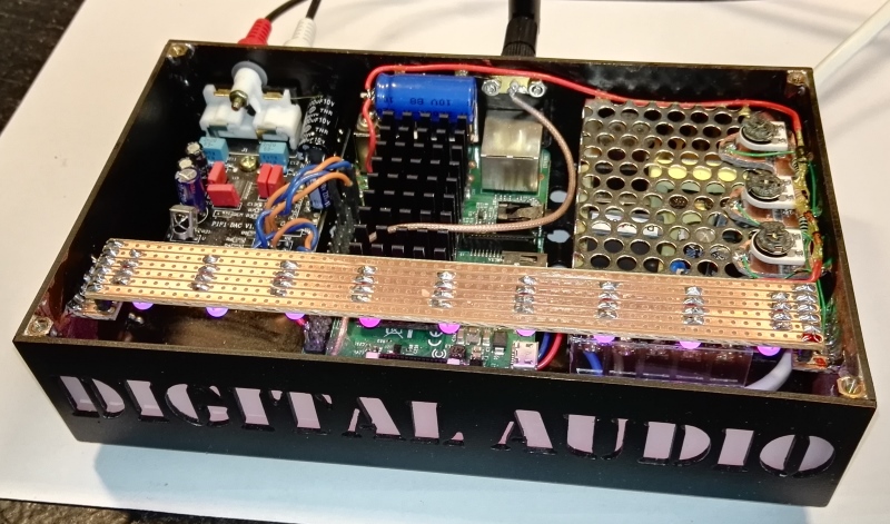
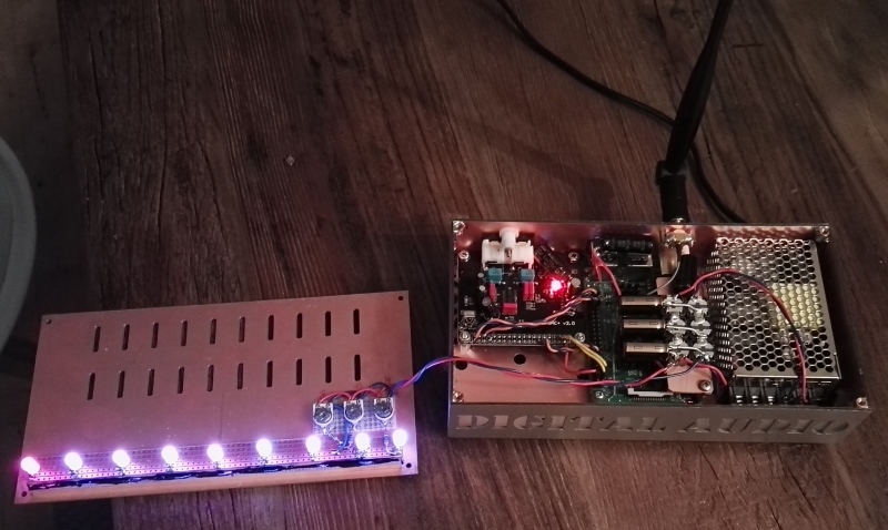
LED board added, note connectors on each side, so it can be removed, this way better access to SD card, in case upgrade of firmware is needed.
Glue acrylic in place, test led brightness and color, i used 3 trimmers for power to each RGB led,
i did not know exactly what color or brightness i wanted, so it is nice to be able to change it
I go for strictly analog low-tech here, dont want any PWM stuff to add noise.
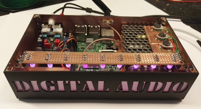
all done
done-front-led_010215.jpg
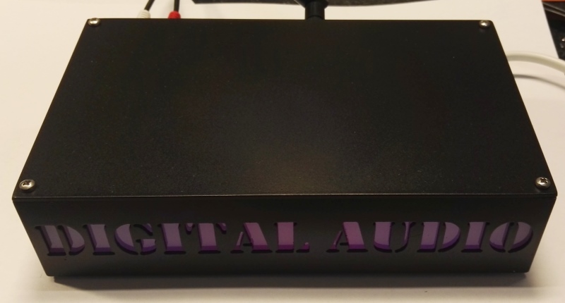
done fully assembled
done top
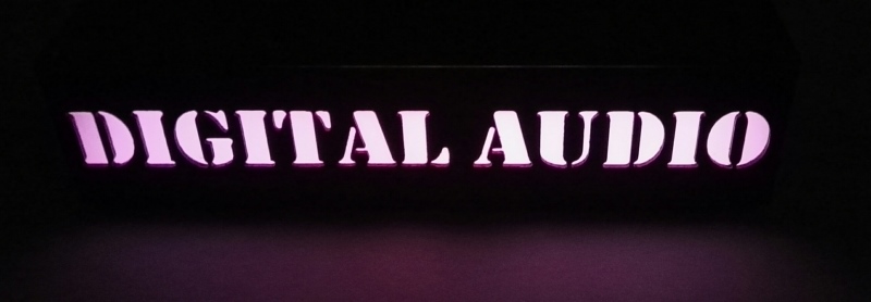
light at night, the green status indicator on the PI can actually be seen from the front too
PI3 I2S connections to a PI1 sound card using a PCM5102A DAC,
please note some pi3 soundcards need 1-2 signals more, like the types with PCM5122
The sound card used here, IS modified so it works correctly.
---
AFTER WORD:
ready made software images for raspberry pi can be found at www.runeaudio.com www.moodeaudio.org www.volumio.org
I spend years to play with them all, they all got a tiny twist of difference, so test them and see what you like the most.
the one you stick with, please donate to say thanks, they spend huge work into this, and got great support too, worth paying for.
THERMAL ISSUES:
The design you see above, made the CPU too hot:
cause1 : shiny heatsinks do not radiate heat as IR
cause2 : system inside closed case with no moving air = result same as no heatsink
cause3 : inside of case also very shiny = also reflect heat, so outside of case was Cold, inside burning hot.
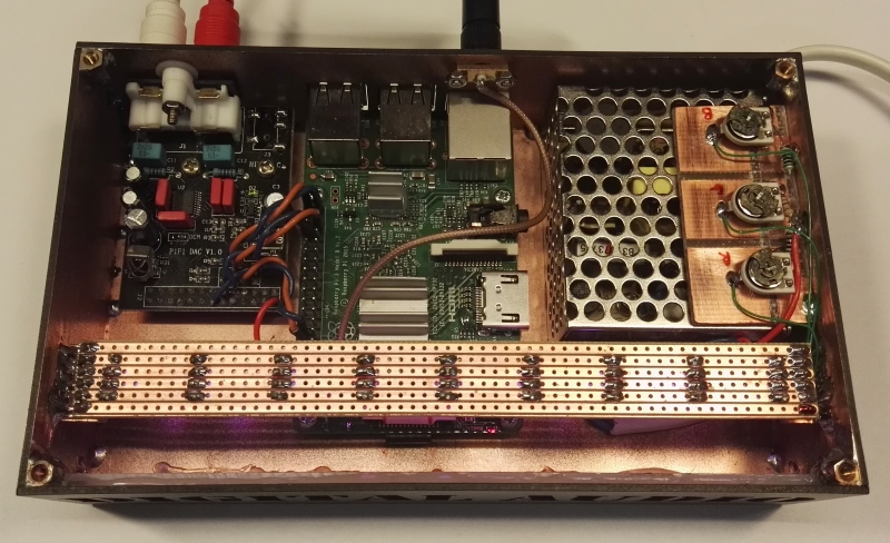
fix1 : changed heatsinks to larger Black coated types = radiate heat as IR much better, even if air dont move.
fix2 : painted box Black mate inside to pick up IR, and drilled air holes in bottom of case, and lid with holes.
NOW the CPU is 22 C colder and i am happy.
the new super sized black heatsinks, and note the black painted inside of case.
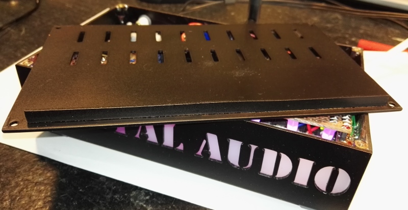
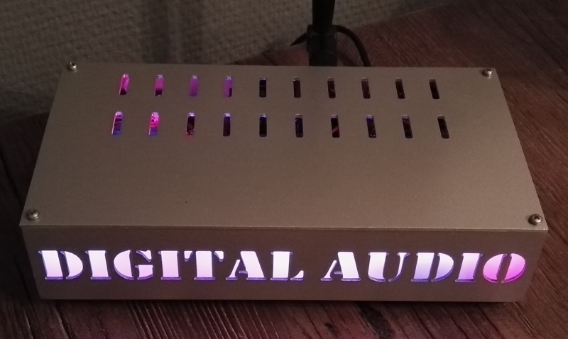
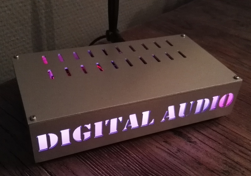
new lid design, milled nice looking stribes 3 x 15 mm each, and 20 of them
soldered a thinn line of pcb in the front to hide light stribe from the tiny gab.
-----------------------------
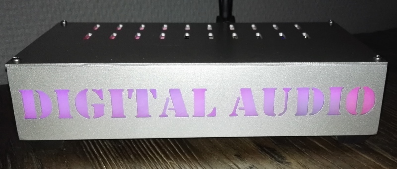
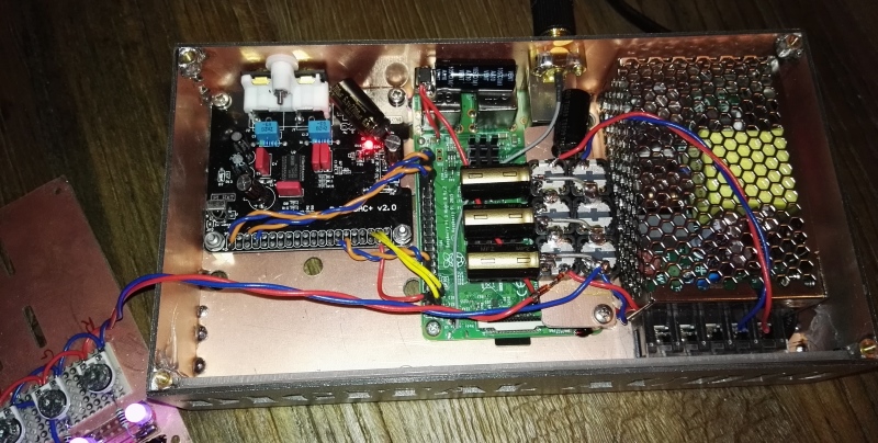
I made one more for a friend. he painted it a special silver color to match look of other audio equipment.
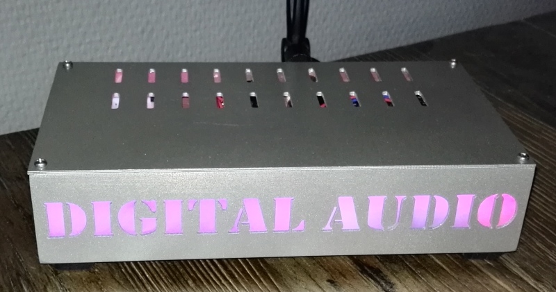
size : 100mm deep, 190mm wide, 40mm height
this one is 20mm wider due to bigger PI3 sound card.
mk815.jpg

this type of powersupply gave a little bit of barely detectable noise in low volume setting 3-10 on UI and full volume on audio amp !
in combination with USB harddrive current usage, so a few caps was added to the usb supply, and main input supply got a little filtering coils too
and also one extra large cap at the DAC, just to be sure all was fine after this visit.
The sound card used here, IS also modified so it works correctly.
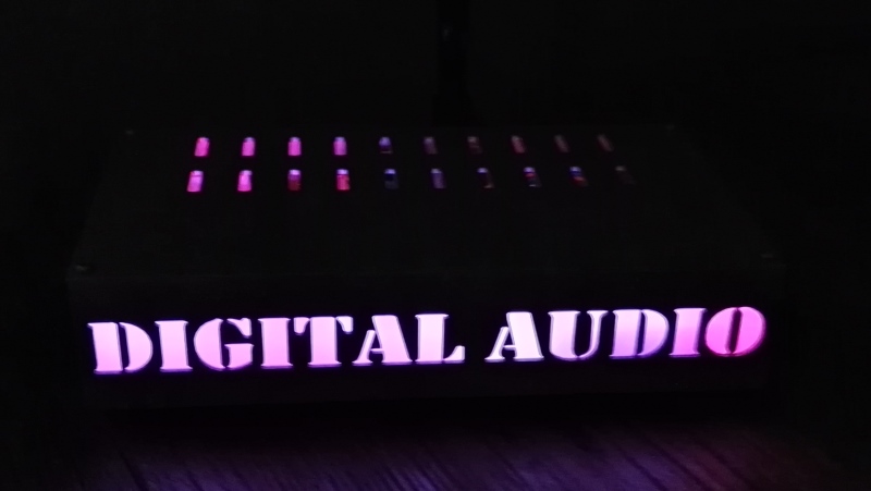
night look
-----------------------------
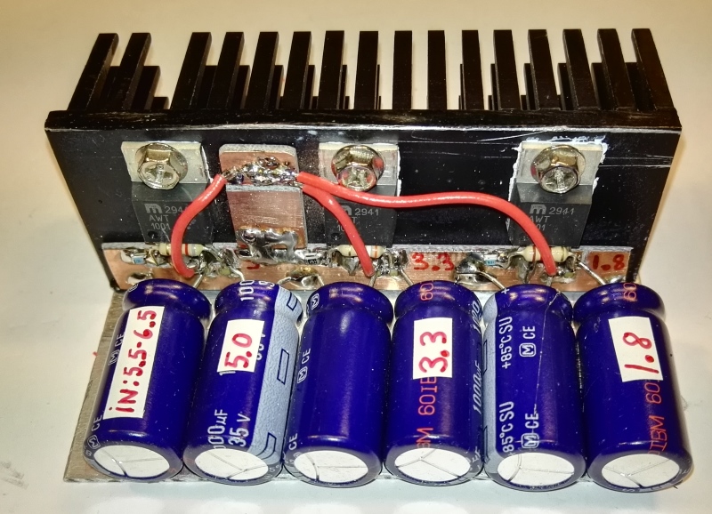
Before mounting the caps, I use 3 x LM2941, smd caps and smd resistors, I made all supplies a little bit to high voltage initially
this way trimming down to exact voltage is much easier by adding a higher value on the GND resistor (220 ohm)
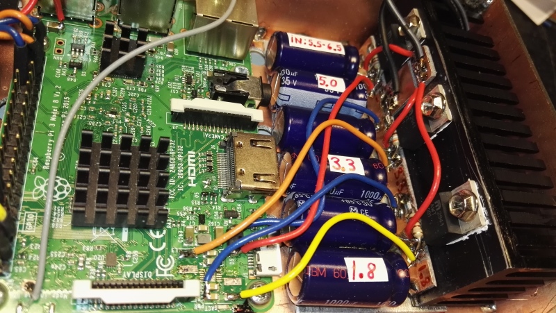
installed into the casing, use as SHORT wires as possible, every cm counts !
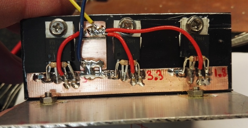
Be sure to double check all voltages at the caps, BEFORE you remove the IC, some PI versions have other C numbers on the caps
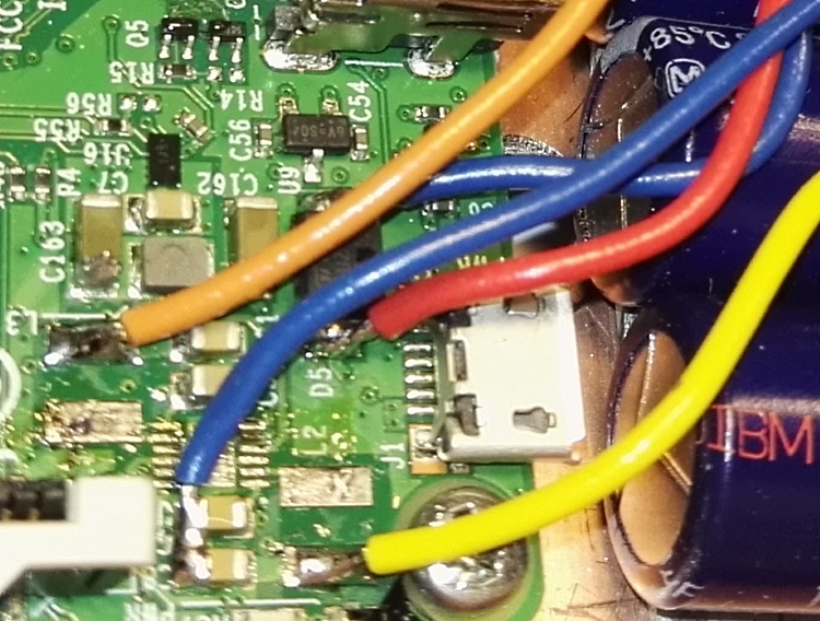
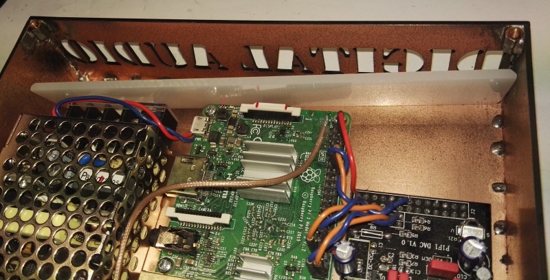
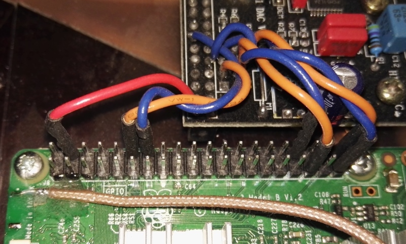
a close up on connections for a Raspberry PI 3 - B - version 2
Yellow 1.8V - Orange 3.3V - Red 5.0V - Blue GROUND
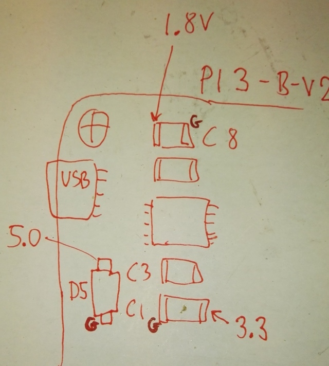
my hand notes made while double checking original PI before the hack.
i suggest to remove the two inductors before the IC, this way easier access, use two soldering irons with large tips,
so all pins on each side can be heated at same time, the IC got large ground pad for cooling, so it takes a bit time to heat it up.
-----------------------------
2017 Thomas Scherrer OZ2CPU,
thanks a billion times to OZ5DZL for pcb milling service, job well done (sorry about all the broken drills)
If you found this page usefull, why not consider donate a bit.. see my contact page.