 www.webx.dk Start page
 MY little Radio Control page
 UHF RC system
 UHF RC system, Hardware manual 4.02 RX 4.00 TX
HARDWARE TX UNIT, V4.00 with powerup feature
the TX unit is designed for 5-25V supply, consume 1.5Watt at any input voltage (500mW RF out) due to the low loss switchmode converter
input voltage must be at least 6V to be able to get full power out is selected
the TX needs only 3 signals : GND=shield, +supply=red, PPM=black.
Damage will ocur if reverse powered or if supply higher than 25V
all TX units are shipped fully cased and fully programmed and tested,
the customer must purchase a trainer plug seperatly, make sure it fits their RC unit type, find pin out information and solder it them self.
a good link to RC units and their pinouts is here : http://users.belgacom.net/TX2TX/tx2tx/english/tx2txgb3.htm
Some customers have repported the 3.5mm jack pin out to be different:

1 GND, 2 not used, 3 PPM in/out (this is the way several Graupner JR Spectrum users have found it working)
Normally this kind of connector is not numbered but named like this
1 shield or body often used as ground, 2 tip or top, 3 centre or middle pad or many other things.

For X9303 or similar JR, Graupner, Spectrum systems, use a mono connector to power up the unit in student mode with internal RF disabled
1 GND, 2 PPM out
Normally this kind of connector is not numbered but named like this
1 shield or body often used as ground, 2 tip or top
Thanks to RCTime for this info:


hope this helps DX8 and others with similar units
----

If your RC system have a multi pin trainer connector, it most likely have powersupply output too,
look in RC unit manual and connect the 3 wires to LRS correct, please measure the supply voltage is correct so you dont damage anything
if you swap supply voltage to the LRS you will fry it ! if you short power from your RC unit you will melt and fry connections in it !

Some RC units have only the PPM signal out, normally in a 2.5 or 3.5mm jack, look in RC unit manual to find the pin connections
the LRS TX unit can be powered with a seperate battery back like pictures here, it is important to connect power and signal ground like this
ABOUT BINDING !! if you use a SEPERATE battery pack for the LRS TX box, keep the RC unit ON all the time, and power only the LRS TX box up and down while you press the button,
is explained in the normal binding procedure,
now binding will work, since it is the LRS TX unit at power up - button check, that activate binding..
The 4.00 TX, in NORMAL case, and in PRO case
 -
- 
All TX units have from factory installed a 3 power level switch 0.5W 1W and 2W
The 2W setting is now improved and can be used for longer duration
I suggest 2W is used for 30 min max, on TX normal case
and 3 hrs max with TX PRO.
The powerup feature is designed to be used only af a plane saver in case default power is just under limit,
It is not smart to fly far away until radio control is lost and then trust the powerup feature will always save you !
it is ment as an emergency back up that can if lucky save you, same as a seatbelt or airbag :-)
The booster have the option to be supplied with different supply voltage and can then give you a 6 to 10dB
power up change when a switch is pressed, that will give you enough power change to be able to make a full save plane
in case all RC range have been used.
Bind / Failsafe storing, push button is located to the left of BNC connector
TX BATTERY LIFE
The TX unit draw about 1.5W as mentioned at 500mW out, to find the current it draw we use ohms law,
Watt / SupplyVolt = Current, the supply voltage can be anything from 6-25V. Example with a 3S lipo: 1.5W / 11V = 0.126A
To find the time you can run with a given battery size,
take your battery mAh and divide with current usage also in mA
Example: 1000mAh / 126mA = 7.9 hrs, remember to keep a good safe margin, some batteryes like LIPO do not like to be fully empty.
When using the powerup feature input supply power will also go up ! the unit have about 30-40% efficiency, so an easy rule is the input usage
is 3 times as much power as the output power. At 2W RF out, the unit consume almost 6W, this means 4W is wasted as heat, and input current is
0.75A at 8V, and 0.5A at 12V, and 0.25A at 24V, most RC units run at 7-10-12V I guess.
The TX unit can deliver 500mW out at only 5V as supply voltage, it will stop working at 3.3V or under.
For 1W and 2W output, you need supply voltage of at least 6V. Maximum is 25V !

HARDWARE RX UNIT (version 4.02 RX LR Long Range for FPV flights)
The RX unit is designed for 4-6V supply (4 -5 nimh cells or 5V BEC)
Full performance is expected in the 4-6V range
Supply current at 5V = 128mA
RF senstivity = -113 to -114 dBm at 10% BER (or better)
Damage will ocur if reverse supply voltage and if supply is higher than 9V.
Two LED indicators show what antenna is the best right now.
Two MCX coax dipole wire antennas are supplied with each RX this type
This new receiver have much better input filter and will now handle video transmitters at 900 1300 2400MHz much better than anything you have seen before
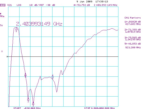
Attenuation at 430 to 440 MHz passband under 0.9dB
Attenuation at 900MHz 47dB
Attenuation at 1300MHz 75dB
Attenuation at 2400MHz 53dB
This is much better over a saw filter but also bigger and more expensive.
RX RSSI
This section is ment to be used by experts and is a bit technical.
the CH12 connector have 4 pins have the pinout from left:
RSSI analog out - ch12 or PPM out - Servo Power Supply - Ground
the RSSI signal can be used with OSD systems
Channel 12 PPM or Servo signal
The NORMAL version of the firmware in all receiver types,
is made to auto switch from PPM out to servo signal channel 12 out, on the ch12 connector,
this way the RX can be used with 12 normal servoes if needed.
However some new microcopter projects now support 12ch PPM for all sorts of usefull features
a SPECIAL PPM fixed out firmware is available on request, ask for this when ordering,
or upgrade the RX your self is also possible, using a serial port level converter.
Note about RSSI signal loading : a version 4.02 LR RX have RSSI signal buffer
so you can load it with whatever you like directly, no need for series resistors
The RSSI voltage from the LRS RX is about 0.5 to 1.0 Volt from bad to best, you need to calibrate your OSD so it readout 0-100% for this voltage range
or bargraphs or what ever is possible, I expect this should be explained in your OSD or logger manual.
RX SERVO Supply current
Normal servo connectors and supply connectors used for RX systems, are designed to handle max 2A each
so in a multible servo system remember to add all peak currents
and be sure your supply connector is not overloaded. Large scale planes often uses powerboxes to solve this normal problem
you can parallel some servo connectors supply and ground to be able to handle more supply current to your system
RADIOSYSTEM
This system uses wide band frequency hopping in the two free ISM bands 433 and 444MHz.
To make this system secure each tx units in same area must use different ID code
so they will use dirrerent frequency and different hopping system,
more systems can opperate on the same field at the same time with 100% performance.
(it is possible to use any frequency sets in the 410 to 450mhz band on request)
RANGE
The calculated line of sight range is 100km.
To give you a good safety margin stay within 5km (with 500mW standard version and little whip)
the 7W booster give you at least 15km range with whip antenna.
both ranges mentioned can be tribbled or even more, if you use a larger and better antenna or even a directional type on the TX side.
RANGECHECK
can be done just like conventional RC systems, in this case simply unmount the TX antenna, and set it to low power,
then expect 4-10 meters of range, then check you have same (short) range with motor on/off,
and with video cams and video transmitters on/off, if no change in the range result, then mount TX antenna again and fly.
INSTALLATION
The TX box is a small metal case 58mm wide, 72 mm long, 27 mm height, it is supposed to be mounted on your convertional RC unit.
but it can also be mounted some where else using a long cable for the power and PPM signal.
The RX is installed just like any conventional RX

The two RX antennas (on LR receiver) is supposed to be mounted so at least one of them can always be seen from ground,
mount the two antennas 90 degree angle to each other.
If receiver antennas are mounted horizontal in plane -
then longest range is also achived holding tx antenna horizontal and vice versa.
it could be smart to mount one antenna vertical and one horizontal if possible.
it is ok to cut the antenna wire and solder (same length) stiff piano wire so when vertical mounted it will be straight while flying.
KNOWN LIMITATIONS
Landscape variations and noise polution in the flight area is known to shorten the range of any wireless link.
Use at least 1/10 of the distance as height. for example at 3km distance stay 300meters up to get full range.
Standard transmitter with 500mW and the standard quaterwave antenna will give you a 3-5km range, in normal city area,
may be much longer in areas with no noise polution.
WARNING and DISCLAMER
when using any wireless RC system bad things can happen, batteries can fail, hardware can fall out of planes,
and many other things, what ever bad happens, I can not be held financial or personal responsible,
you agree to this by using this system !
-------------
Trouble shooting LRS install and FPV stuff in general
1:
Turn off all video transmitters and cameras in your plane,
try the bind and store failsafe, and then double check all servoes
are nice and stable and fast reacting, if this is true you proceed to 2
if not fix or complain or ask me
2:
turn on video tx and camera and gps and osd, see if any change in perfect servo movement
try to make the mentioned range checks in the manual, if all pass goto 3
if rangechecking shows problems you have a bad video tx or bad camera system or problems with
power supply or problems with video tx radiate bad harmonics, you must try to fix that somehow.
fix problems and goto 1:
3: fly and be happy
more tips and tricks here
-------------