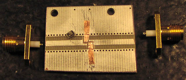
the parts needed for test of the filterGPS-murata-SAFSE1G57KA0T05R00.pdf
Also see the video wireless page if you like.
Foreword:
To get the most out of any receiver and transmitter installation, it is
important that the receiver can perform without interference or blocking from
the transmitter.
The closer they are placed together the more problems you will get. In this case
I need to have a EM406 GPS receiver with broadband patch antenna and ultra high
sensitivity,
located 40cm away from a powerful 2.4GHz video link, that was impossible
without modifying the GPS unit, since it was not equipped with any kind of
band pass filter in its input before its hi gain amplifier, and this amplifier is
not designed for hi power signals.

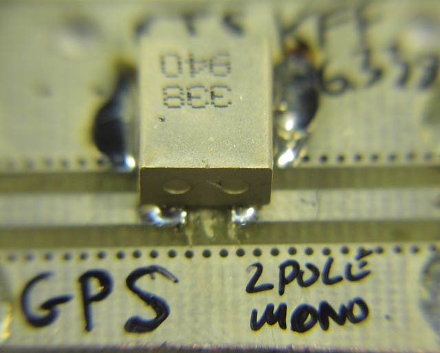
the parts needed for test of the
filterGPS-murata-SAFSE1G57KA0T05R00.pdf
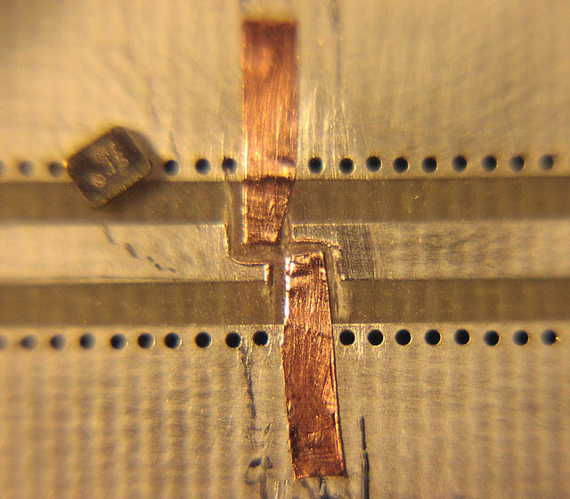
the filter is really small, under 2x3mm, and special care was taken to keep the
50 ohm track as close as possible to the filter.
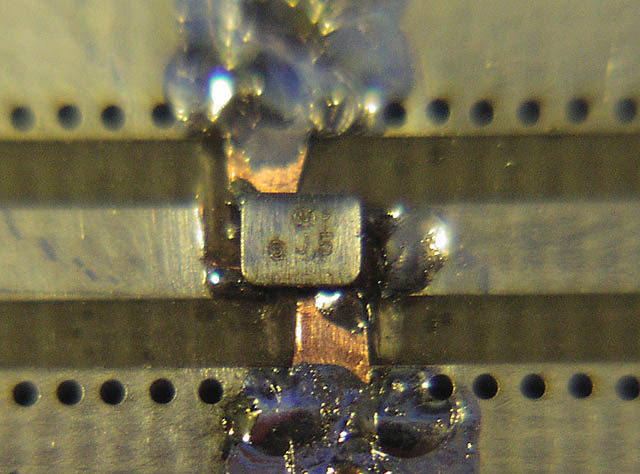
soldered in place, not that easy to do by hand.
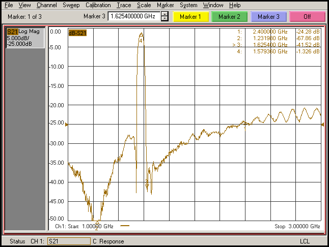
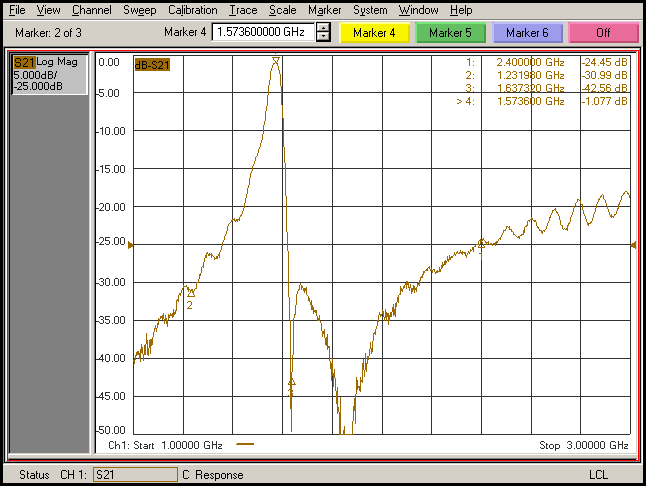
Measurement result, shows 1.3dB insertion loss, we can live with that, but quite
disappointing only 24dB at 2.4Ghz
Field tests showed much better GPS performance with this filter attached, some
lock problems and low sat count,
the field test also shown much better results when 2.4GHz transmitter turned
off, and much more satelites.
I tried to attach a 10dB attenuator to the transmitter, now the GPS with this
filter performed perfect,
so now I know we need more than 24dB but not more than 34dB :-)
-----------------------------------
this filter is a bit bigger, but perform also better on some parameters like
insertion loss filterGPS-CTS-KFF6338A.pdf
nice with only 1dB insertion loss, but lacks at 2.4Ghz, this filter was not
designed to attenuate for 2.4 by the way.
so for this purpose another useless filter.
---------------------------------
using 0805 coils and High Q capacitors (really expensive but good stuff)
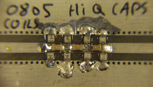
this filter is quite small, the solder area is about 2.7x2.7mm adds about 1.7pF
to the equation !
--------------------------------
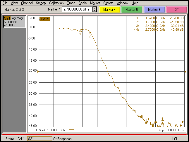
using 1206 coils (20% tolerance) and cheap 0805 1pF (10%) 100V capacitors.
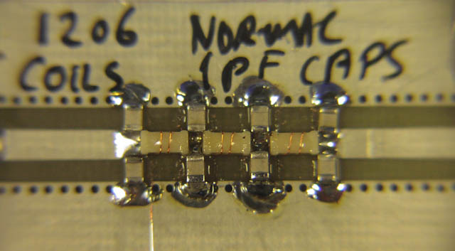
This filter is a bit bigger, the two caps in the middle bottom is actually two
1pF on top of each other.
so 10 x 1pF caps are used in total. all coils are 6n8
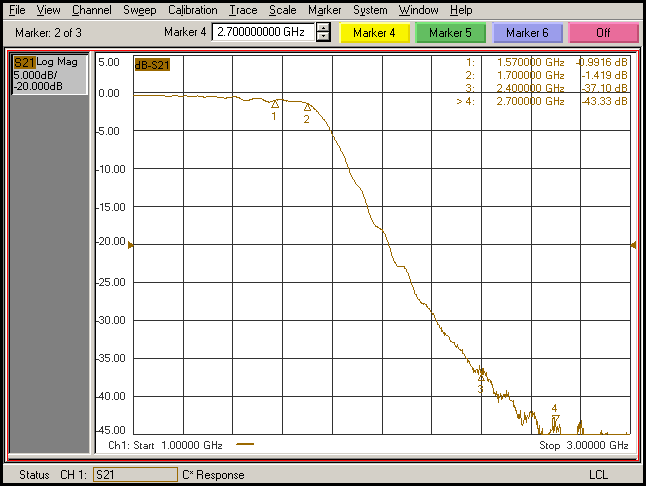
This filter attenuate 37dB at 2.4GHz and has actually under 1dB insertion loss,
quite good,
Specially when the track itself including two SMA connectors made 0.2dB before
cutting and mounting the components.
There is made a nice margin to the filter poles be coarse 20% and 10% components
are used.
--------------------------------
by the way same thing with the EM406A it has a
slightly changed input circuit, but still no real filtering or protection
against blocking.
The A version seems to be slightly more sensitive, it is difficult to prove but
I have compared two 406 with two 406A within the same few minutes,
using the exact same placement and setup, and it seems like I have 1 or maybe 2
satelites more with the A version, maybe I was just lucky with the
timing ?
you know how the sat display go up and down all the time.
I had no possible way
to power them all 4 up at the same time and compare signal levels on them all
simultaneously.
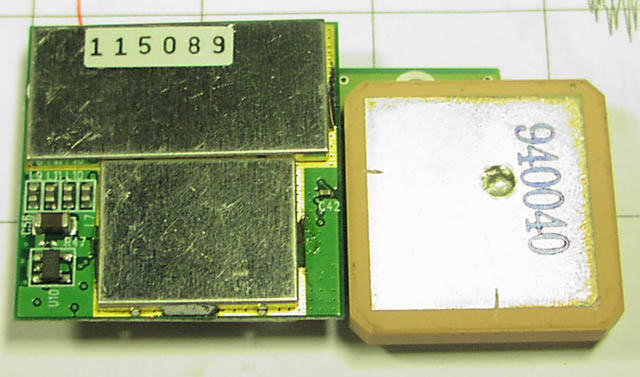
EM406 with filter 1
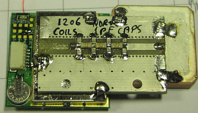
EM406 with filter 2

EM406 with filter 3, low height is important, will make it smarter to integrate
into wings and such.
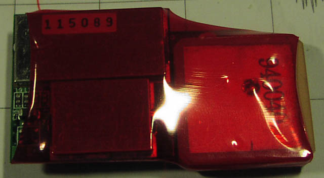
Done.
--------------------------------
A 7 pole low-pass filter perform better then conventional readymade filters for
this type of application!
but this type of filter can not be used if the video transmitter is operating
at 1Ghz, then the frequency spacing is too small.
Some people reported they had no problem using same type of GPS and same TX module at
same frequency,
maybe their transmitter is not as powerful in real life ? or mounted in such way
or direction so less power go in GPS direction ?
For me the most optimal antenna placement was GPS straight up, and 2.4Ghz TX
also straight up, since bottom of my plane could not be used to point the TX
antenna down,
but in such case it would have generated a bit less signal into the GPS and a
bit more
signal down to ground, so maybe think about that also.
I suggest placing the transmitter and GPS as far as possible from each other,
and if used together with other receivers like for an RC plane,
again keep the RC receiver away from video TX, so actually: keep sensitive stuff
together for example RX
and noisy stuff together like motor controllers, switch mode power supplies and
transmitters.
------------
Thomas Scherrer OZ2CPU March 2007