
 Start page
 PC modifications mainpage
 Homemade temperature LED display for PC
Since I started my watercooling prejoect, I have been verry interested in how well it perform,
the only way is to measure all temperatures before and after,
The motherboard temperature sensors is useless unacurate, so I'm using LM50B
By using this LM50B sensor I get 1 C of real accuracy
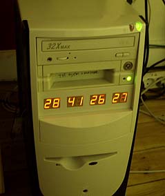
I use a PIC16F876 to drive a four two digits LED displays, the PIC16 has 4 analog inputs with 10 bits resolution,
now I can display 4 temperatures at the same time to monitor performance :-)
I monitor CPU, Chipset, GFX card, Harddisks.

The biggest problem was actualy to make the four holes. what a mess

The PCB is just normal vero board, used often for simple proto types.

Here is the top side of the PCB, Big picture
The four 3 pin connectors are for the four sensors, the 5 pin connector is used for in circuit programming.
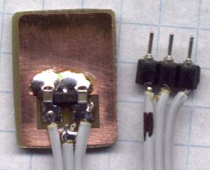

The small PCB with LM50 and filter capacitors, note the lines on the paper is 5 mm


Here is the same type sensor mounted on "minimount" PCB.

Nice display ??
Here is the schematic good old handdrawn original..
Here is the schematic Re-Drawn Maybe you like this better :-) OK, comments for the circuit:
You can use any number of LED displays: 2, 4, 6, or all 8, depending on how many temperatures you want to display,
LED display type must me common cathode, FET can be any N-FET type you have, I have used IRF530 I had on stock,
NPN transistors can also be used if you dont have fets, then remember to mount a 1k resistor on each base inpus.
Each sensor input connector is protected using a 1k resistor, so you can connect sensors with power on,
nothing will burn if you connect it wrong.
Only calibration requred is the refference voltage, it need to be exactly 2.5600 volt, I have used a super stable regulator,
but an LM317 can also be used to make 2.56 volt with if that is what you have. DOWNLOAD The HEX file for the PIC16F876.
The 5 volt supply is taken from a free harddrive power connector, no need to regulate it, 4.8 to 5.2 will work fine.
This complete circuit with 8 all digits consume about 100mA. Good Luck.

My homemade chip set watercooling block with temperature sensor.

The rear side of my GF2 was transfering the heat from the GPU really good, so I figured this is a good place to mount my sensor,
Now I can make some before/after temperature measurements.

Close up of the small smd sot-23 sensor and filter capasitors on small pcb,
glued with sensor down to harddisk metal side.

I have glued a LM50 Temperature sensor in the hottest component inside my PSU, the 5 volt double diode.
Now I can measure before and after temperatures to prove the efficiency of watercooling.

After a few minutes the temperature was 40.42 Celcius and rising !! (-500mv to get celcius value)
By using this LM50B sensor I get 1 C of accuracy and two decimals resolution
so it is really easy and fast to see if there is a rise or drop in the temperature after I change something.
After 2 houres (I turned powerdown off on both harddisks) the temperature stabiliced at 47.7 C.
One disk consume 850mA at 5 Volt and 750mA at 12 volt that is 13.25 Watts each !!
I have two mounted right on top of each other, no wounder they get HOT
I will also install water cooling on both harddisks and then noise isolate them. Then we will see what their temperature will be :-)
www.ourpcb.com/what-happened-to-national-com.html">
The LM50 sensor, look up its datasheet on TI.COM