 www.webx.dk Start page
 MY little Radio Control page -
X-Twin Night light LED
MY little Radio Control page -
X-Twin Night light LED

 X-Twin RC plane transmitter code info and modification
X-twin little RC plane radio interface hacked, Complete data pakage about
33mS long.
Repeat cycle = (200mS #C) (166mS #B) (242mS #A)
All TX on same channel. ON/OFF keying AOK AM 27.145MHz
RF Pulse Bit 1=1296uS - RF Pulse Bit 0=689uS - DelayY = 659uS - DelayX=1296uS

Total of 18 bits are send:
1 bit Lead in, 6 bits fly ID, 4 bits Left Motor, 4 bits Right Motor, 2 Check
bits, 1 Stop bit.
The lead in bit is always 1, and the stop bit is always 0
I can not explain why the DelayY in the ID bits are all 659uS, when the DelayX
in the left and right motor string are 1296uS long.
I guess it is actually an error, the two short delays when the bits are 1 should
also be long, to keep the DC value constant.
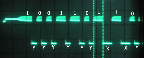
Here more zoomed in, on the lead in and ID sequence.
The Lead-in pulse is changing from 1.3mS to 1.8mS depending on the other bits,
also quite strange !
_______________________________________________________
OK here are all the bits send in all compinations:
L ID LM RM C S (TRANSMITTER#C)
1 001101 0000 0000 110 Gas OFF
1 001101 0011 1001 010 Gas LO - stick to Left
1 001101 0011 0011 010 Gas LO - stick to center
1 001101 1001 0011 010 Gas LO - stick to Right
1 001101 0101 1011 000 Gas MID1 - stick to Left
1 001101 0101 0101 110 Gas MID1 - stick to center
1 001101 1011 0101 000 Gas MID1 - stick to Right
1 001101 0111 1101 110 Gas MID2 - stick to Left
1 001101 0111 0111 110 Gas MID2 - stick to center
1 001101 1101 0111 110 Gas MID2 - stick to Right
1 001101 1001 1111 100 Gas MID3 - stick to Left
1 001101 1001 1001 010 Gas MID3 - stick to center
1 001101 1111 1001 100 Gas MID3 - stick to Right
1 001101 1001 1111 100 Gas MID4 - stick to Left
1 001101 1011 1011 010 Gas MID4 - stick to center
1 001101 1111 1001 100 Gas MID4 - stick to Right
1 001101 1001 1111 100 Gas MID5 - stick to Left
1 001101 1101 1101 110 Gas MID5 - stick to center
1 001101 1111 1001 100 Gas MID5 - stick to Right
1 001101 1001 1111 100 Gas MAX - stick to Left
1 001101 1111 1111 110 Gas MAX - stick to center
1 001101 1111 1001 100 Gas MAX - stick to Right
All those bits measured with trim at center position.
--------
Some measured bits with trim to the Right..(TRANSMITTER#C)
8421 8421
L ID LM RM C S
1 001101 0111 0111 110 Gas MID2 - stick to center
1 001101 1000 0111 010 Gas MID2 - stick to center - trim R1
1 001101 1001 0111 000 Gas MID2 - stick to center - trim R2
1 001101 1010 0111 110 Gas MID2 - stick to center - trim R3
_________________________________________________________
L ID VM HM C S (SENDER#A)
1 001100 0111 1101 000 Gas MID2 - stick to Left
1 001100 0111 0111 000 Gas MID2 - stick to center
1 001100 1101 0111 000 Gas MID2 - stick to Right
All those bits measured with trim at center position.
Some measured bits with trim to the Right..(TRANSMITTER#A)
8421 8421
L ID LM RM C S
1 001100 0111 0111 000 Gas MID2 - stick to center
1 001100 1000 0111 100 Gas MID2 - stick to center - trim R1
1 001100 1001 0111 010 Gas MID2 - stick to center - trim R2
1 001100 1010 0111 000 Gas MID2 - stick to center - trim R3
__________________________________________________________
How to calculate the checksum:
all is setup in 2 bits portions, the first 4 bits of the ID are not used.
Example:
L ID LM RM C S
1 001100 1010 0111 000 Gas MID2 - stick to center - trim R3
|
| | | |
00-10-10-01-11 = 00
Simple subtract binary with roll over, does the job
another example:
L ID LM RM C S
1 001101 1010 0111 110 Gas MID2 - stick to center - trim R3
|
| | | |
01-10-10-01-11 = 11
another example:
L ID LM RM C S
1 001101 1001 1111 100 Gas MAX - stick to Left
|
| | | |
01-10-01-11-11 = 10
_______________________________________________________

Here is the original transmitter inside.

The measuring point for the scope pictures.

To make the X-Twin controlled by normal
cool computer transmitters a little
microcontroller converter is needed,
this will convert a normal PPM signal into the special 18bit stream and calculate the right
checksum.
Here is the schematic including a homemade 27Mhz AOK AM transmitter. ((D1/TxD=
Debugging codes with PC program serial port.))
User info on the 35Mhz PPM side:
Channel 1 = Motor 1
Channel 2 = Motor 2
Channel 3 = Plane ID (-100% = A, Center=B, +100%=C)
Channel 4= Update Speed (-100%=Normal, Center=Normal, +100% SUPER FAST, ONE PLANE
AT A TIME ONLY)
This can be changed to whatever you like, read below !!
The Mixing is made quite simple on the normal 35MHz computer transmitter:
Motor1 = (Trottle -100%)+(Aileron 40%)+(Elevator 30%)
Motor2 = (Trottle -100%)+(Elevator 30%)+(Aileron 40%)
Ch 3 = Aux1 = 3 position Switch L or whatever switch you prefer
Ch 4 = Aux2 = 3 position Switch G or whatever switch you prefer
By making all mixing in the normal 35MHz computer transmitter, it is now much
more flexible,
and can be changed and optimized by the users.
The super fast repeat mode is using all the bandwidth for only one plane, (no
delay at all) so remember this when others are near !
but in this mode you will get instantly motor speed response, so the plane will
react much faster and be much more easy and fun to fly.
Pictures of the X-Twin plane Outside : 01 - 02 - 03 -
04
Inside pictures 013 - 014
- 015 - 016 -
017
Battery spec : Fullriver 452026P
Capacity=130mAh Weight=3.6gr Discharge current=1A

To test the software we just ripped an old 27Mhz RC transmitter and added a
microcontroller

5V regulator for the micro on the back side.

All just glued fast together.. for testing.

Nice long antenna ? well it is the original from one of my X-Twin transmitters.

Now this little converter can be added to ANY transmitter with student out PPM
and Power.

Memory 20 is now in use ! Later I found out this 27MHz transmitter had too
little output power,
since it was impossible to change it to give more output, I simply took the
board from the original Xtwin transmitter,
Like this:
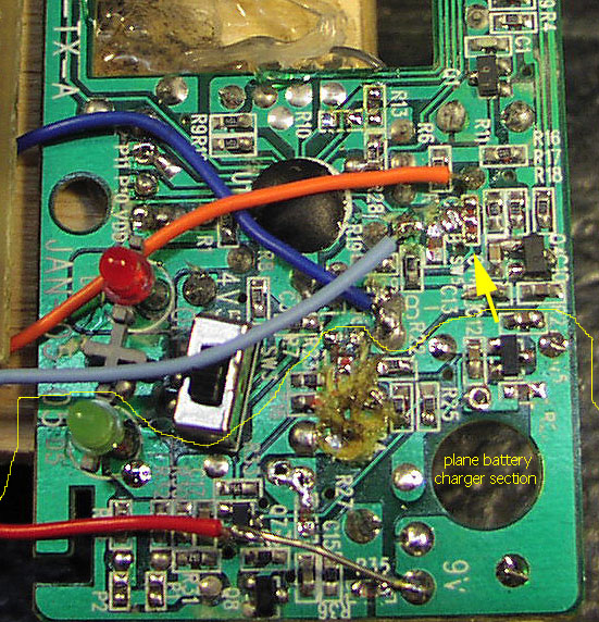
To use the original transmitter board, Remove all original wires, Cut the track
that goes under the 1 in R14 text, Remove R14,
Cut the track that goes under the top circle of 8 in R28 text, remove solder
connection ABC marked with yellow arrow.
Orange wire = 18bit pulse from Tiny2313 pin 15
Light Blue wire = Transmitter on signal from Tiny2313 pin 14
Blue wire = GND,
Red wire = +7V to +9V from computer PPM transmitter.
You dont need to remove other parts, like I have done in the charger section, I
just wanted to minimize current consumption.
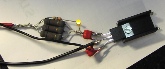
Another way to charge the planes since they need 5.0V top up voltage, a current
limited 7805 can be used,
3x100 Ohm in parallel = 33 Ohm in series with the input, an LED with 330 Ohm,
that is about it.
Input voltage is 12-14V as usual that we all have handy.

5DZL: my homemade charger schematic, remember to adjust the open voltage to 5.0
V
becoarse there is a "stupid" diode inside the plane, to prevent external discharging and
to prevent some charges to be used (damn)
Flying time changed alot when using our own chargers, now: 15-20min, before:
5-10min.

5DZL: here is my X-Twin charging

5DZL: remember the small cheap and lousy 27Mhz car transmitters ? add a Tiny2313 micro and use it to control the X-Twin !
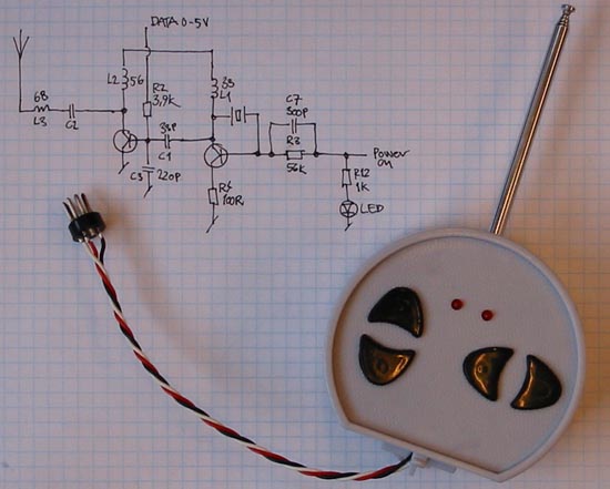
5DZL: The transmitter schematic of those "nice" little things, the original CPU
has been disabled
and supply voltage almost tribbled to get more transmitter power.
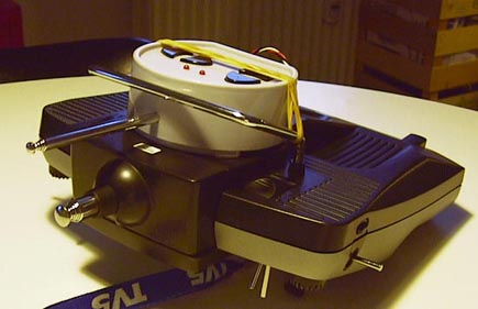

5DZL: you will get a long way with rubberbands, fast, simple, easy.

5DZL: The easy way: cut a few tracks from the original CPU inside, add Tiny2313, that is it..
Note the plug that fits into my EVO9 transmitter.

Here is a screenshoot of the PC setup program Xtwin Config V1.3 we use to
change settings inside the Tiny2313 converter.
The invert functions are not implemented in the 2313 firmware due to program
size limitations.
When a valid PPM signal is available the Input monitor will show all channels,
This makes it easy and fast to find out what channel number you will need to
assign to each function.
If the user dont have a funky computer transmitter with crewl mixers, the
internal mixer mode can be used
to make the Tiny2313 converter make all the mixing, and then use the 3 normal
inputs, Throttle, Aileron, Elevator.
The Exclusive switch changes the update speed, from normal to super fast,
but remember in this mode only one plane can fly at the same time.
It is possible to make the Xtwin "channel" fixed and update speed fixed to
whatever you like, if a 3 channel PPM transmitter is used.
Free HEX file and Free PC software download version 1.3
Fuses: internal OSC 8MHz, don't divide by 8.
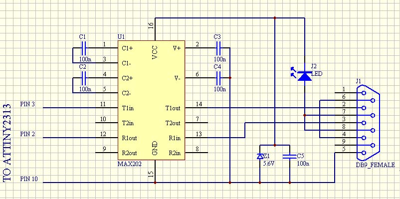
Here is the RS232 level converter you need to use our PC software setup program.
Video clips flying with our Tiny2313 converter and Royal Evo:
dzl-85.avi 763kb - dzl-86.avi 677kb
- dzl-87.avi 323kb - dzl-89.avi 765kb
- dzl-93.avi 1184kb
WARNING: You will get addicted to Xtwin

5DZL: After a few weeks you will need to have them all in your collection.
(edition 12 Aug 2006 Thomas Scherrer OZ2CPU) - (All AVR software made by: OZ5DZL Nikolaj Mřbius)
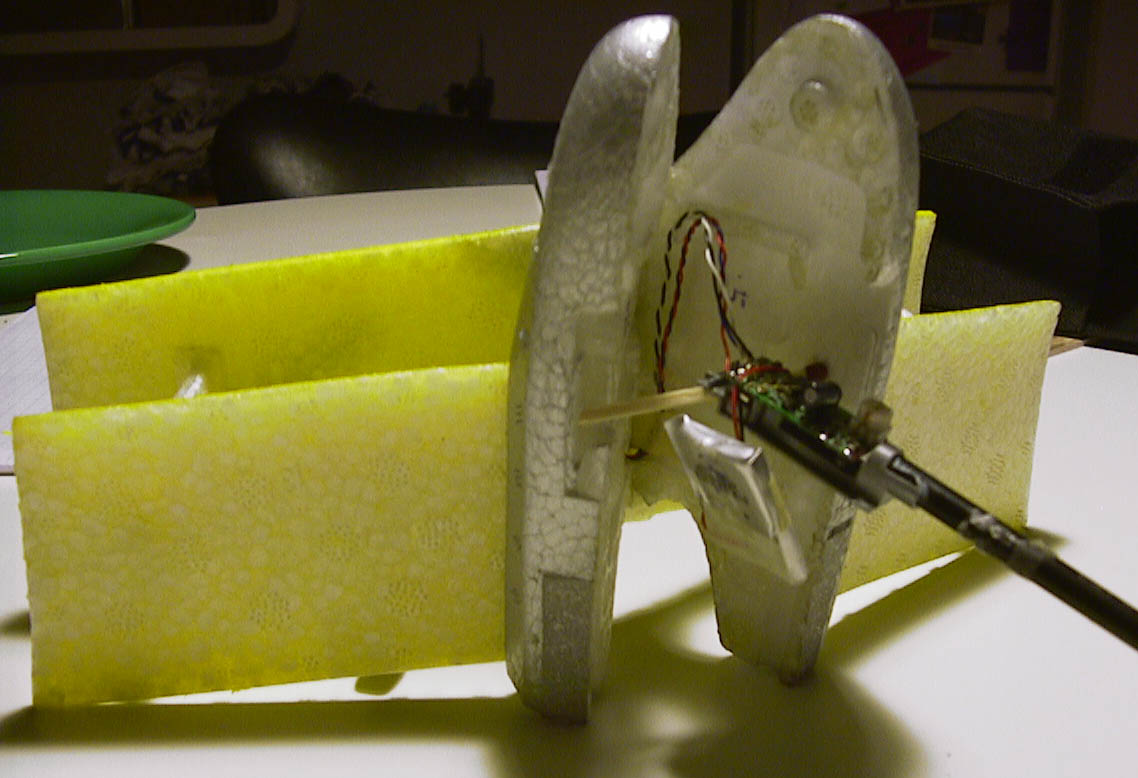
Here is one of many emails we have got about this,
From Markus, Dornach, Switzerland :
Great article on controlling X-Twin planes with a PPM transmitter!
I planned to do that on my own when I found your pages on the web –
so I dropped my effort and just rebuilt your project.
Super software on the AVR, works great with my EVO.
I just used open wiring and the standard transmitter,
together with a glue gun and a small plastic housing.
In the attachment you find pictures of my hardware.

