
The radio side of the board, this one is configured as a receiver, see the servo plugs.
see also PA stage for ultra long range
see the new version 3 design UHF link project
This system RC control system samples PPM frames with up to 8 servo information's, and encode this digitally with a complicated checksum,
The receiver part decode it and generate up to 8 servo pulses, now we have a jitter free system.
In Denmark 10 radio channels in the 433 - 434MHz band have been legally assigned to be used for RC control of models.
it is legal to own and use transmitters with up to 500mW without any license or approval.
(I am not alone on this hardware/software project, dzl.dk is in charge of most of the SW)
Both parts use the same board with same hardware, only difference is software !
and the transmitter part the PPM signal from the student plug goes into one special "servo" port.
The transmitter is boosted in power using an external amplifier, read more about this below.
The radio side of the board, this one is configured as a receiver, see the servo plugs.

The microcontroller side. sorry I did not bother to clean the board after
soldering :-)

Our AVR microcontroller programmer uses a quite large IDC6 connector, so it was
smarter to make an adapter using micromatch.
The final versions will not need this programming and debug connector.

Channel numbers, Ground +5V Signal


First test flight system, we took the PPM and power signal from student plug,
into a board with "TX" software.

Inside the transmitter box we mounted a 250mW power amplifier, using halve the
legal power we want to see the range achieved.
here we have plenty of space and weight is not critical, so a normal ICD6 can be
used for software upgrading.

Receiver inside a test plane, the antenna is connected using a plug, so the
receiver can be upgraded fast or changed to another type if needed.


Top layer, The radio side with no components mounted.

Bottom layer, Microcontroller side, and 2.5V regulator,
note the four 100mill spaced pads, it's 5V, GND, RX, TX rs232 payload two-way data,
will be used later for all kinds of extras you can imagine.
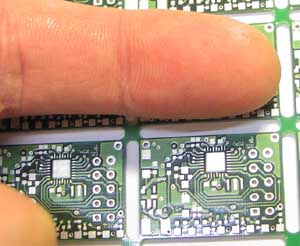
See the "receiver" is only stamp size


Here goes the 8 servo plugs, some can even be configured as analog inputs,
for measuring voltage, current, or whatever we can figure out in the future.
since an "RX" board mounted in a plane can actually transmit also,
it makes sense to keep all possible things open.
There are 3 pins for each servo, just as usual on all other RC receivers.

A real professional PCB was made, using 4 layers, Bottom Layer show here, click
to zoom.

Top Layer shown here, click to zoom

Test PC software was made to tell signal quality on each channel,
We use a complicated hopping scheme to make the RC system immune to jamming and noise.

Pinouts of the MICRF620 module I am testing, together with the pin out of our
homemade MICRF506 module (erly version)
The MICRF620 module is really cute, only 0.8 gr and measures 14 x 12 x 3 mm.
all is done for you, but ok a bit more expensive compared to the 506 chip + components + board + mounting + trouble
more info here: www.micrel.com/page.do?page=product-info/radiowire_bluechip.shtml

The power in mW vs frequency curve I could not find in the brand new datasheet, no problem I made it my self
The 7, 6, 5 is the power level inside the 620 module.
Power vs voltage, I have measured on the MICRF620 and MICRF506:
with 2.87V VCC (under the 3.3V absolute MAX value)
Lev 620    506
0  10nW    7nW
1  310uW  600uW
2  630uW  1.2mW
3  1.2mW  2.4mW
4  2mW    4mW
5  3mW    6mW
6  4mW    8mW
7  17mW   19mW
----------------
with 2.50V VCC
Lev 620    506
0  10nW   6nW
1  200uW  370uW
2  400uW  740uW
3  770uW  1.5mW
4  1mW    2.8W
5  2mW    4.8mW
6  3mW    7mW
7  11mW   13mW
----------------
with 2.00V VCC
Lev 620    506
6  2mW     4mW
7  4.8mW   8mW
I have several 506 boards, this is the best one ! the worst gives halve this power,
-Thomas Scherrer OZ2CPU and Nikolaj Mřbius OZ5DZL (2006-2007)