

Older Discontinued versions Still supported and still fully compatible offcourse
Explain all names on my pages and about FPV please read this one first before asking questions
MCX wire antenna detailed for the receiver
Antenna Plane Install Recommendations ![]()
Video clips from customers
Pictures from customers 2008-2009
Pictures from customers 2010
Pictures from customers 2011 NEW
see also 30W PA stage for ultra long range
see also old version 2, we have test flown V2 for over 3yrs now
see also 30W booster-in-action, test flight with video goggles and long range receiver antenna
The 7W booster for trible range is also avaiable NEW Version 4 released December 17 !! ![]()
The 7W booster for trible range is also avaiable NEW Version 4 PRO released Jan 19 2010 !! ![]()
Customer Radio Range Competition
Customer Survey NEW
The new PRO versions ![]()
RCgroups forum thread about this system alot of good information to read here, #1 post about purchase and order and prices
DISTRIBUTORS:
Electronicarc.com SPAIN Distributor, both local sales and local support
ReadyMadeRc.com USA Distributor, both local sales and local support
TrueRC.net CANADA Distributor, both local sales and local support
shyau.com.tw TAIWAN Distributor
Estore Rotterdam FPV systems & R/C electronics Rotterdam the Netherlands Distributor and local support
MIRROR SITE:
http://www.readymaderc.com/lrs_mirror/uhf-link3.htm MIRROR SITE ONLY TO BE USED IF MAIN PAGE IS DOWN, BOOKMARK


Different kits exist: the more you purchase the more you save, here shown SET 1 LR and SET 2 LR


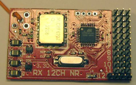
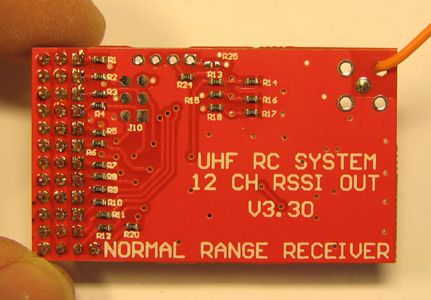
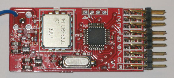
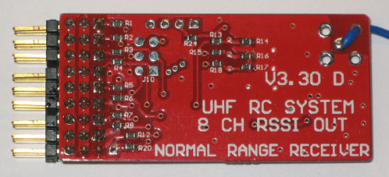
Here shown SET 1 NR Tiny slim 8ch, and SET 1 NR 12ch (this receiver will soon be phased out)
This RC control system is specially designed for RC model planes that need extreamly long range and safety, like: FPV/UAV, large models, and expensive models.
The TX unit samples PPM frames from a normal RC TX unit, with up to 4-12 servo information's, and encode this digitally with a complicated checksum,
the receiver part decode it and generate up to 12 servo pulses, this gives a jitter free system known from all PCM systems.
at the same time this system uses a complex wide band multi frequency hopping (FHSS), makes it virtually imune to jamming,
the ultra fast diversity antenna switching system removes all dark-holes when the angle of the plane to the transmitter changes.
In many contries frequencies in the 433, 434MHz and 444 MHz band have been legally assigned to be used for RC control of models.
it is legal to own and use transmitters with up to 500mW without any license or approval.
(I am not alone on this hardware/software project, Daniel Wee is in charge of the microcontroller SW)



The UHF RC LRS system is tested so far with those RC units:
NOTE a new firmware for the TX units was released DEC 2012, this new 309 firmware handle all ppm modes
even variable frame rates, and alle graupner and Futaba special ppm modes too
Multiplex Royal Evo series 7/9/12 (5 pin DIN 2=supply out, 4=ppm out, 3&5=gnd & must be jumped together)
Multiplex Royal Evo Pro series 7/9/12 (5 pin DIN 2=supply out, 4=ppm out, 3&5=gnd & must be jumped together)
Multiplex Cockpit SX (5 pin DIN 2=supply out, 4=ppm out, 3&5=gnd & must be jumped together)
Multiplex Profi MC3010/3030/4000 (5 pin DIN 2=supply out, 4=ppm out, 3&5=gnd & must be jumped together)
Hitech Aurora 9, take out normal RF module and use module pins from left : 1=ppm, 2=supply, 3=GND (4 and 5 are not used)
Hitech Eclipse 7 (it works fine, see post 5797 and a bit more)
Futaba 6EX 2.4GHz version, is ok (6 pin square)
Futaba 6EX 72MHz version, is ok (6 pin square)
Futaba T7CAP (6 pin square)
Futaba FF7 (6 pin square)
Futaba 8FG
Futaba T9CP (6 pin square) same as T9CHP
Futaba T9ZHP (6 pin round DIN)
Futaba T9ZAP
Futaba 10C (6 pin square)
Futaba 10CG (6 pin square), Sensitive to RF levels, not good to mount LRS TX directly on its back
Futaba 10CP (6 pin square), Sensitive to RF levels, not good to mount LRS TX directly on its back
Futaba 10CAP (6 pin square), Sensitive to RF levels, not good to mount LRS TX directly on its back
Futaba 12ZAP ok in PPM8 & PPM12 no power out in trainer connector (WORKS with 309 FIRMWARE in all modes)
Futaba 12FGA fine in 8ch mode,(WORKS with 309 FIRMWARE in all modes)
Futaba 12FG fine in 8ch mode, (WORKS with 309 FIRMWARE in all modes)
Futaba 14MZ ok in PPM8 mode, (WORKS with 309 FIRMWARE in all modes)
Futaba 14MZP (WORKS with 309 FIRMWARE in all modes)
Futaba FX18
Futaba FX30
Robbe Futaba FC28
Hitec Aurora 9X (more details forum post#12412)
Hitec Optic 6
Spectrum DX5e - DX6i - DX7 (3.5mm jack) see note 1
Spectrum DX7SE DO NOT WORK, ONLY DSM MODE; NO PPM OUT MODE NOT EVEN INTERNALLY
Spectrum DX8 - a little bit of EMC jamming at 2W and if the TX antenna is close to the spectrum (3.5mm jack)
SANWA RD8000 - (5 pin DIN 1=supply out, 2=gnd, 3=ppm out) all 8ch ppm out of the sanwa is ok
Graupner MX12 - MX16S (3.5mm jack) see note 1
Graupner MC22 - MX22 - MC24 - MX24 (3.5mm jack) see note 1B
Graupner 2011 HOTT (3.5mm jack mono 2 contacts, front is PPM and shaft is gnd)
JR 3810 see note 1
JR 9303 see note 2
JR 11x zero (asia version) in ppm8 mode ok, (WORKS with 309 FIRMWARE in all modes), 3.5mm jack or module bay ok
X 9303 the special 2.4GHz version, problem solved see note 3
Turnigy 9X, some seems to handle strong RF signals poorly, like cell phone too close and LRS TX too close, affect display first
ArtTech E-Fly100C, same 3.5mm jack as Graupner, this radio is only 6ch but works fine
Mile High Wings USB interface (a PPM generator) fully compatible
Endurance PCTx (a USB PPM generator.) fully compatible
More planned to be listed here soon, if you test the LRS with an RC system that is not mentioned here,
please inform me so I can add it to the list
WARNING FUTABA owners must read post 1573-1574
note 1:
all LRS TX units shipped after 1 sep 2008 will be compatible
pre 1 sep units can be modified with a resistor, ask me for instructions if needed.
note 1B:
All Graupner (WORKS with 309 FIRMWARE in all modes)
note 2:
all LRS TX units shipped after 1 dec 2008 will be compatible
pre 1 dec units can be upgraded with a firmware file, ask me for instructions if needed.
note 3:
all LRS TX units shipped after 26 march 2009 will be compatible
pre 26 marts units can be modified by changing SMD resistor size 0603 R19 from 68k to 10k, ask me for instructions if needed.
This mod might also work with other JR type of transmitters
Bad Antenna position
Good Antenna position, 90 deg angled
ALL receiver types and versions have GROUND signal near end egde of the board


When ordering, inform me about if you like servo connectors ANGLED or UP
ALL receiver types can have this option, it is no extra cost
If unspecified by you, I will ask or maybe pack what I have available
The UP version: ch12 is mounted with 4 pins for easy access to the RSSI signal
The ANGLED version: ch12 is mounted with 3 pins like all other, RSSI out is in free unsoldered pad
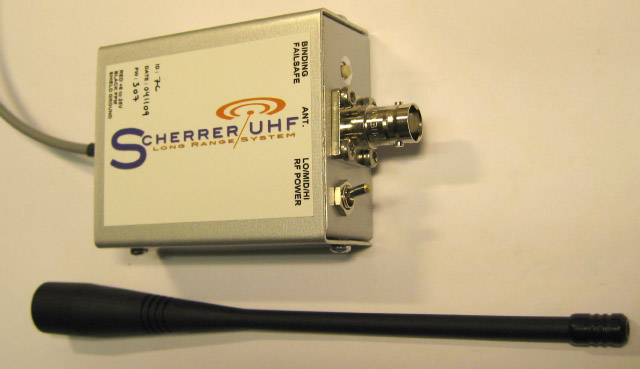
The LRS TX box with antenna
The LRS TX box fit perfectly on the back side of Multiplex Royal Evo 7-9-12 and the Pro types too.
------
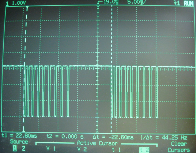

PPM signal, see same REPEAT time even if sticks are moved

PPM signal, the marked area is the dead-time, it will vary depending on sticks position
Video clips:
http://www.vimeo.com/3794673 show how the diversity system select the best antenna signal,
TX side run a servo test program so we can see all updates go fine while shifting antenna.
http://www.vimeo.com/3794162 Instruction video how to bind and store failsafe.
-Thomas Scherrer OZ2CPU. this page was last updated: Oct 2013