 www.webx.dk Start page
 OZ2CPU Radioamateur mainpage
 Homemade electronics Stuff old and new
 230V to 230V isolation transformator with low capacity
www.webx.dk Start page
OZ2CPU Radioamateur mainpage
Homemade electronics Stuff old and new
230V to 230V isolation transformator with low capacity
Foreword:
A very low capacity isolation transformer is very usefull for many analog lab experiments
one classic problem is leak current via scope propes ground, this results in an error voltage into the probe
so one simple solution is to power the scope with a floating free from mains supply, very low capacity in the transformator design is needed
else there not that much less error current at higher frequencies, specially a problem when working with motor controllers or other switchmode designs.
Since normal isolation transformators got 600-800pF from primary to sec side, using two normal transformators back to back it is possible to halve this
since it is a two transformator solution, it also works good enought for low frequency designs, like 50Hz and 100Hz mains things.
This page show how i made my own transformator to power my scope for example.
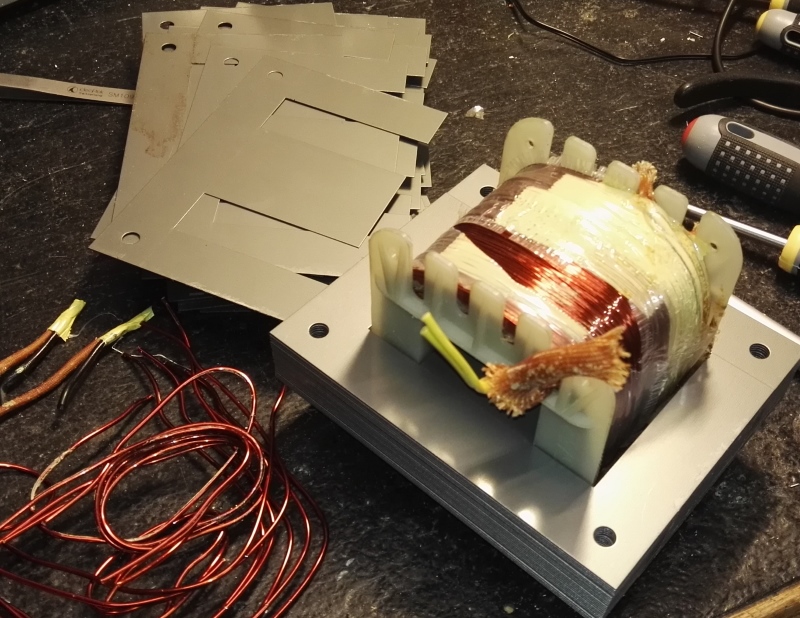
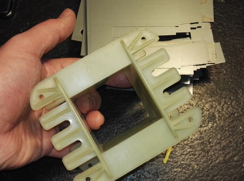
I was lucky to score a used 250VA prototype E core Transformator from my father, it was not coated yet, so it was easy to remove the old windings
it sounded like a good size, since i needed to add 10mm isolation on all sides of the core to lower the unwanted capacity coubling
easy is such a big word, quite alot of kilometers copper wire was used
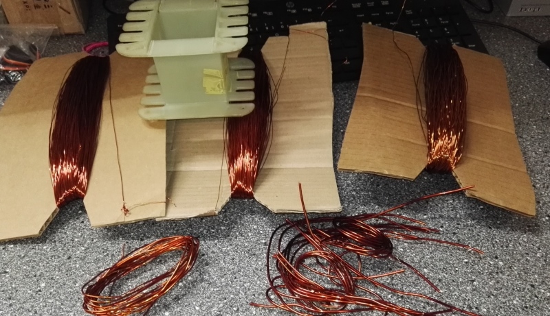
I saved most of it for other projects, free wire nice
perfect size core for this project
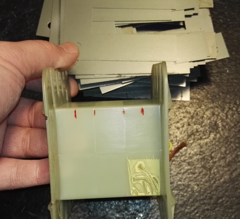
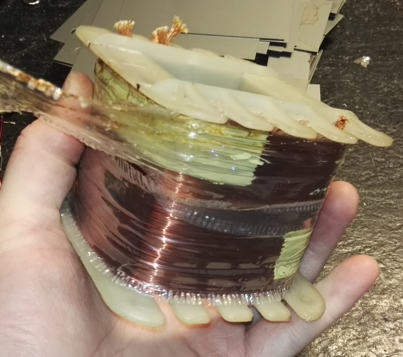
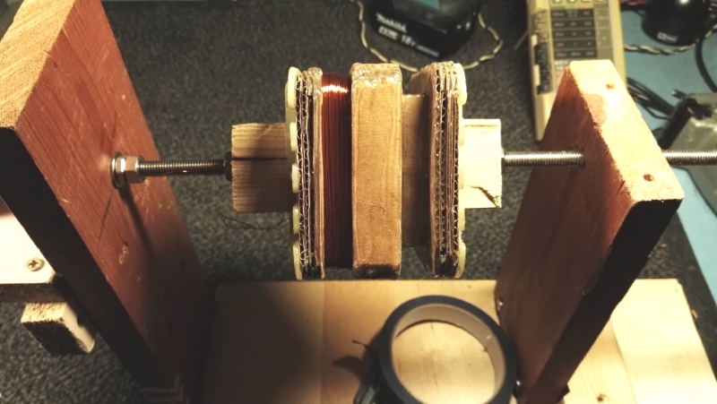
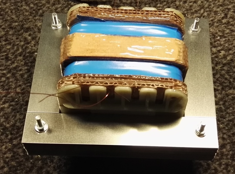
I made a plan, to add cardboard so the primary and secondary windings are as far from each other as possible
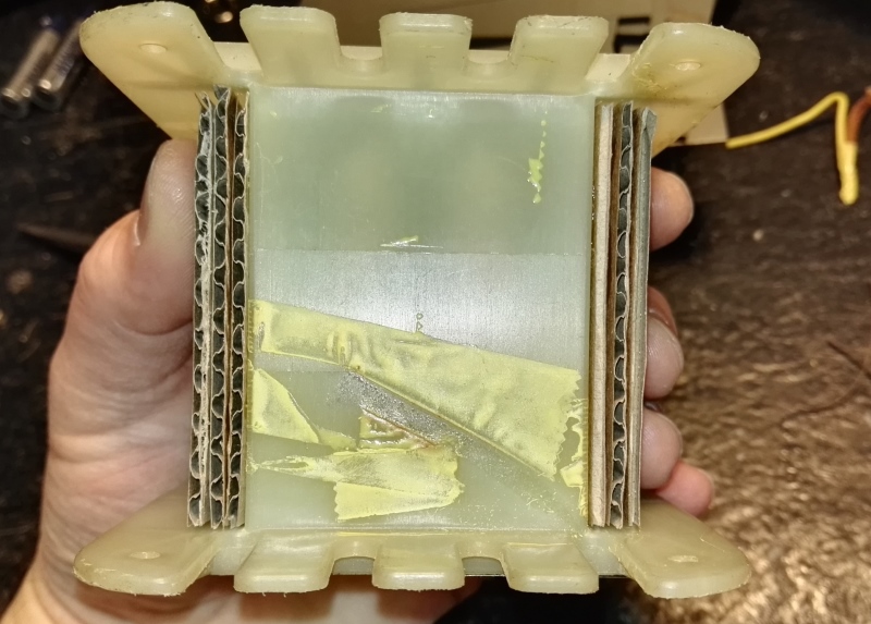
3 layers is about 10mm
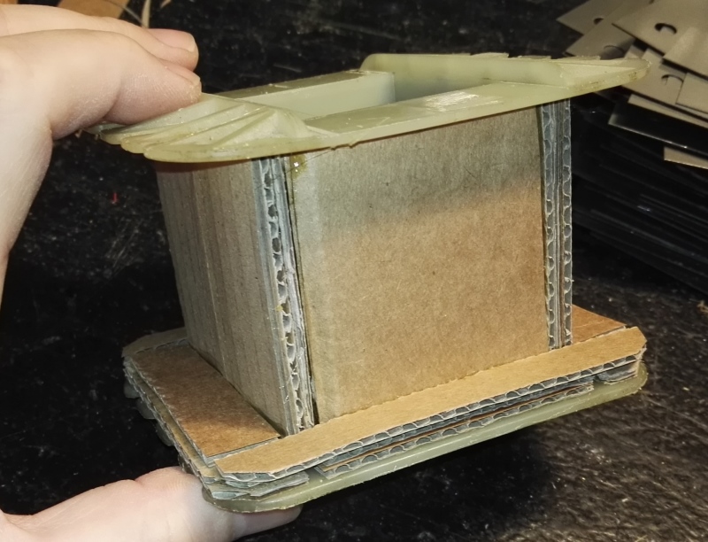
cut clue and fit, easy and fast, i used contact-glue to speed up this project
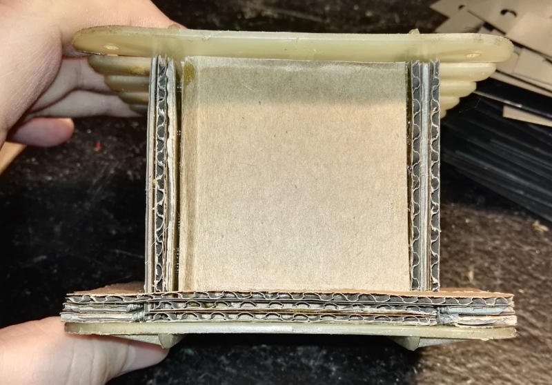
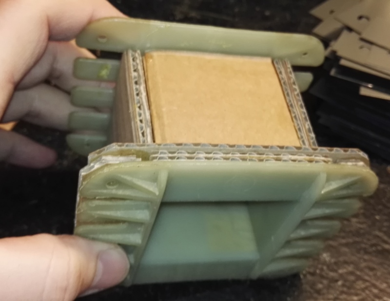
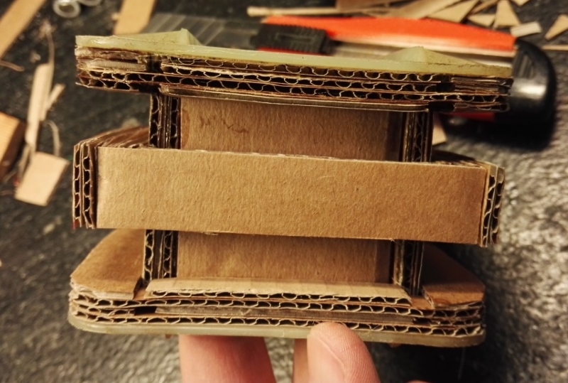
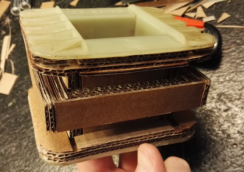
done with the cardboard, now i need to add some epoxy to make it hard and strong
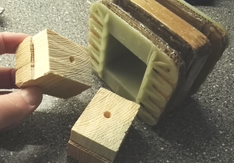
wood ends to make it possible to fit into winding machine
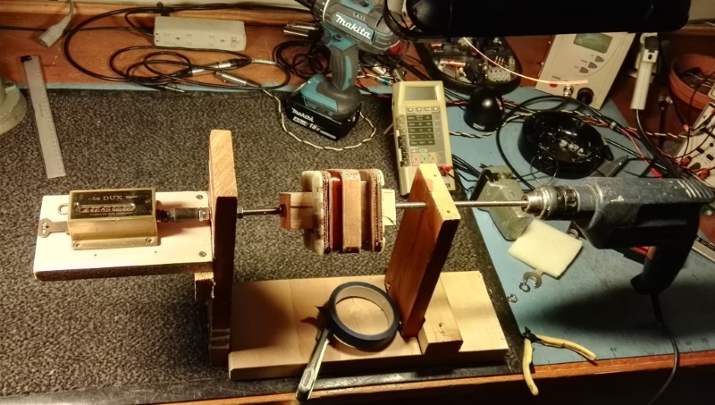
Here we go in the good old winding machine at my fathers lab
Done one side
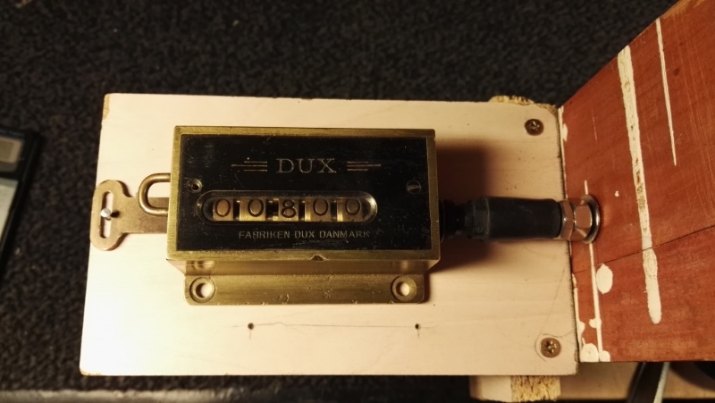
800 turns = 230V = 287mV pr turn, perfect for low idle loss, it is a good idea to run with low flux
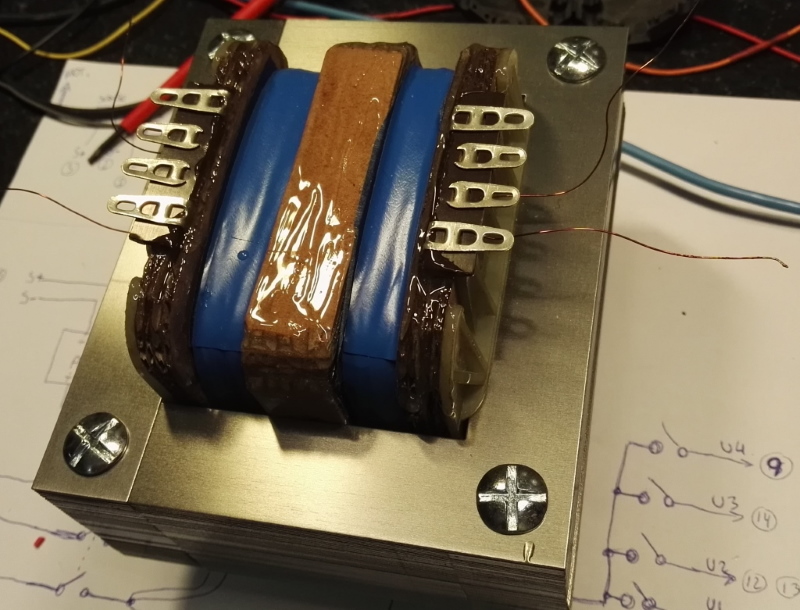
both sides done, 800 turns on each, yes the idea is to make it symetric ratio
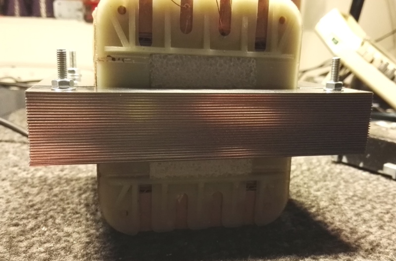
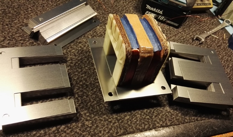
First idea was to try with less iron plates, and add foam as shown to make capacity evem smaller.
the idle loss was too big with halve filled iron, simply due to less inductance about 6watts
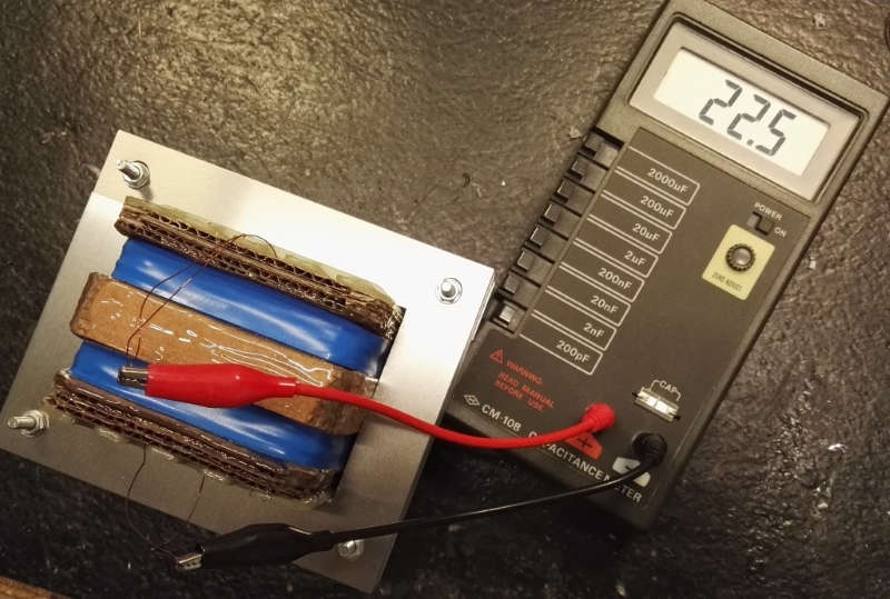
with all the iron the loss dropped to only 1W, and the capacity increased about 4pF so that was ok.
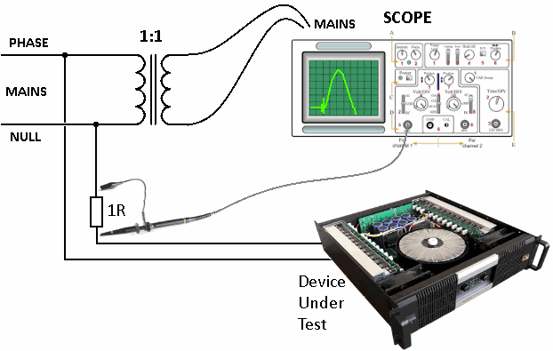
Here is a test setup with a scope, to measure inrush current of an amplifier or any other product.
use a large wirewound resistor 1 ohm is very smart, then 1V on the scope is 1A.
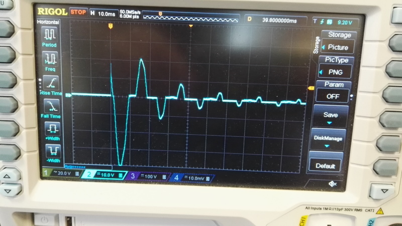
Some products draw very high inrush current,
YES it is 10Amps pr div
this will wear down on/off switches and rectifier diodes and other parts in the first chain of the unit.
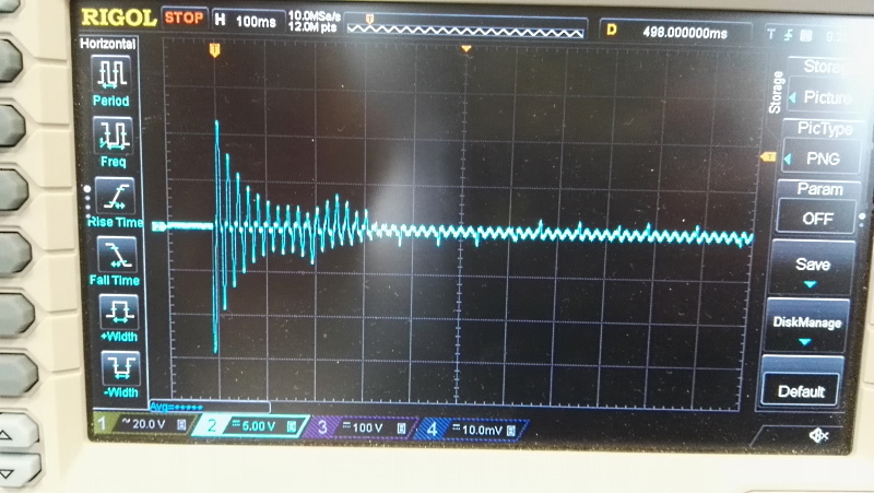
Charge current and time for a large switch mode supply
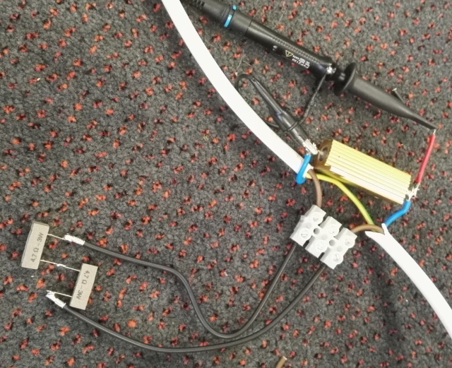
Experiment to see what kind of resistors can be used to limit inrush current
and what kind of value is needed, the resistors will be "shorted" by a relay or fets,
when the DUT main capacitors are fully charged.
-----------------------------
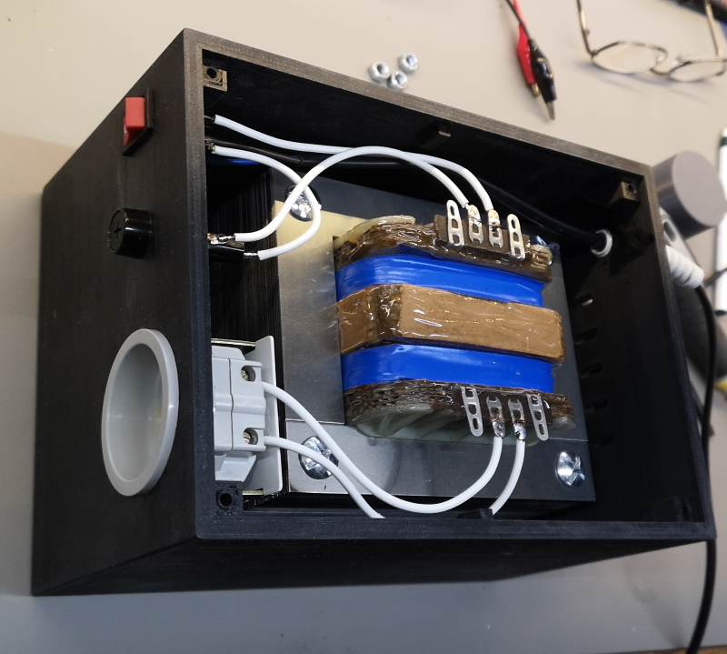
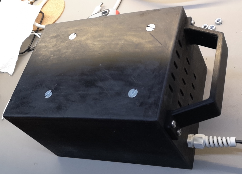
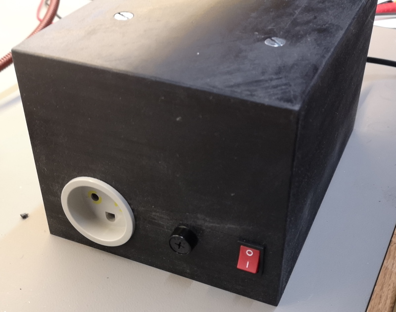
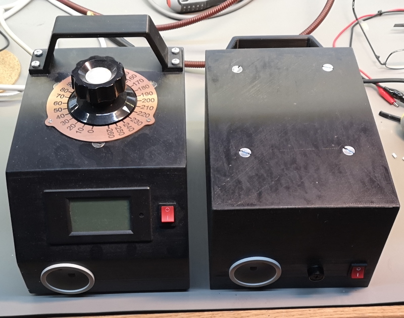
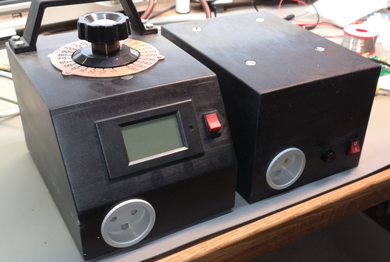
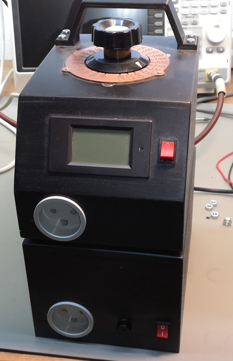
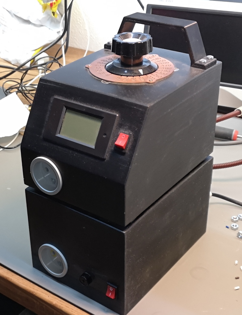
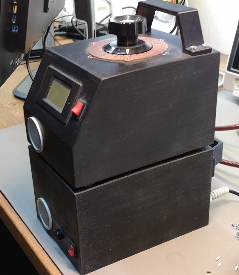
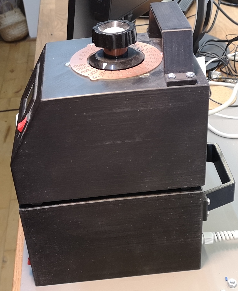
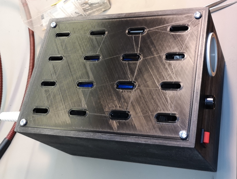
Lets put it into a 3D printed case, that matches my Vario Transformator Design
VIDEO of new toroid design idea with 3D printed parts: https://youtu.be/4rNubfeICOE
.
follow up 1: https://youtu.be/eSZdO_Uca40
.
follow up 2: https://youtu.be/H4WUNACZ-rA
-----------------------------
Thomas Scherrer OZ2CPU 2018-2023
If you found this page usefull, why not consider donate a bit.. see my contact page please.