 www.webx.dk Start page
 OZ2CPU Radioamateur mainpage
 Homemade electronics Stuff old and new
 B&O SN16A lab powersupply repair and fix upgrade info, The unstable voltage fix explained
www.webx.dk Start page
OZ2CPU Radioamateur mainpage
Homemade electronics Stuff old and new
B&O SN16A lab powersupply repair and fix upgrade info, The unstable voltage fix explained
This model is known to be unstable at power up, some times it gives full 30V out, specially if voltage dial is about 15 +/- 5V
and the user must turn dial down and up again to solve this lock up issue, it also get alot worse if output is loaded with a large capacitor.
and it also gets alot worse if the volt potmeter is repaired to a normal single turn type, and then turned fast up.
The cause is simply a design failure, that is addressed is later versions,
but if you own a type SN16A and have seen this issue, here is what you can do
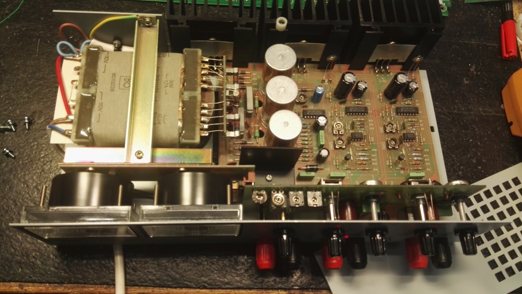
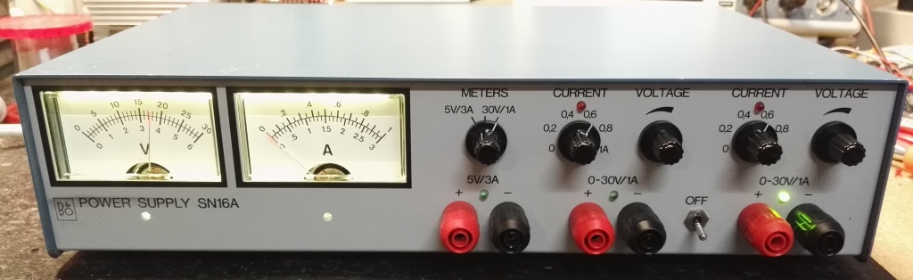
The SN16A inside, note this is the latest model SN16A with earth wire in the mains cable. Erlier varsions did not have this (recommended upgrade)
Original circuit before the fix.
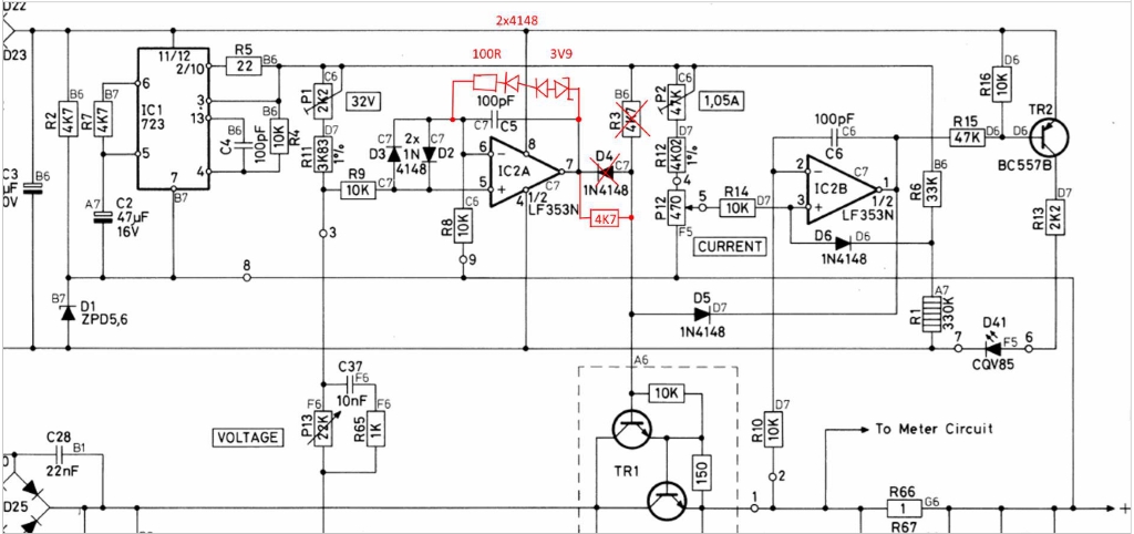
original Schematic in black, the fix is marked with red. i used a 3V9 zener and two 4148 diodes as shown, this way the leak from the zener dont jamm voltage adjustment
The 100 ohm resistor simply limit correction current when this circuit is active, it pull out the opamp from its lock-up where it normally could not exit by it self.
it does this by pulling up the - input, when, and only when the opamp give out, way too much positive voltage, dead simple.
If you are looking for B&O schematics, please go to peel dot dk where a lot of it is available.
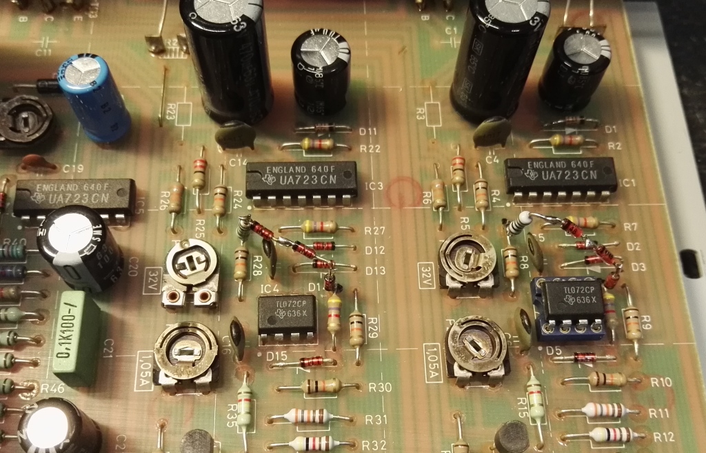
Here both channels are fixed. On this picture it is easy to located the removed R3 and R23
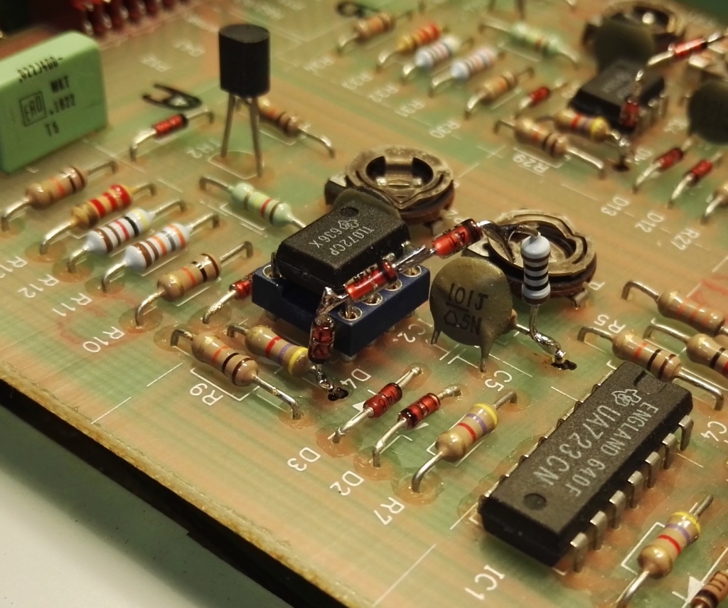
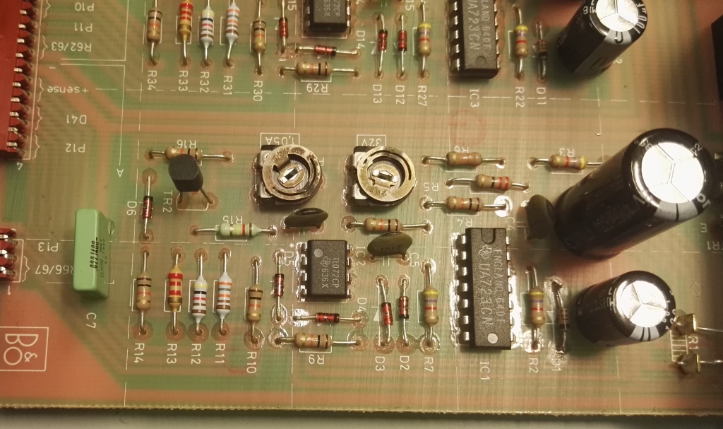
Close up of the fix, note "D4" is now a resistor, easy access to back of pcb via bottom plate removal.
ALSO note where is R3 located, it is desoldered.
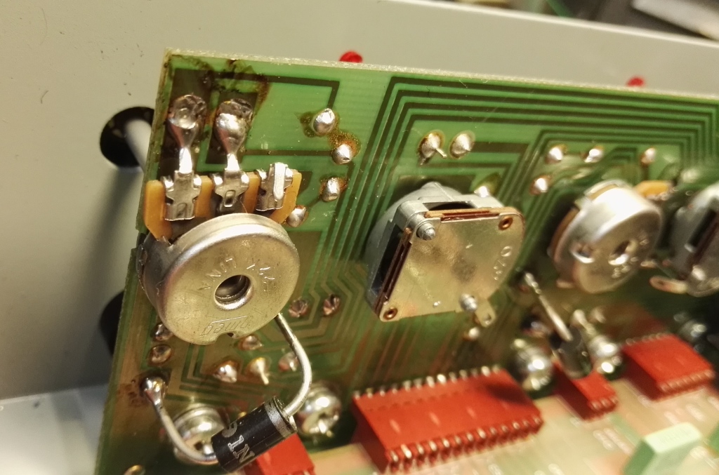
Voltage potmeters are 22k, here a single turn type is used, the original 5 turns are a much better choise, but hard to find this physical size
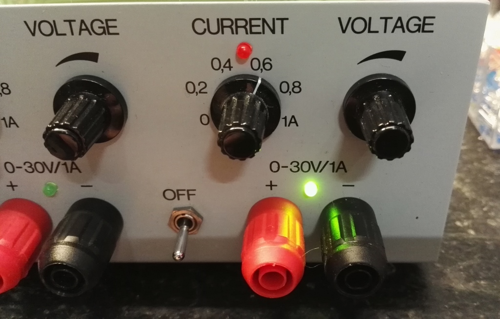
original 3mm LED's are old and worn out, not much light left in them, so I replaced all of them to new types, wow now they are all bright.
The voltage selector indicators as green makes much more user friendly sense.
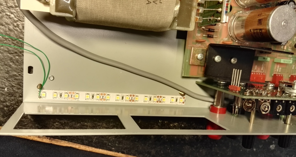
while we are at it, why not add a stribe of warm white LED band under the meters, to make it look and feel more up to date.
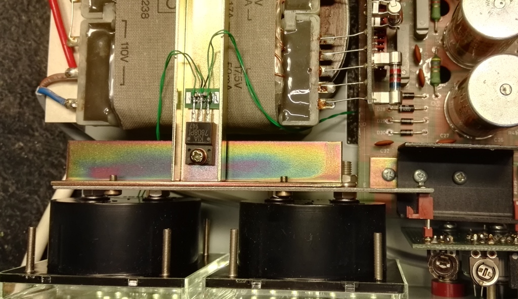
a 12V LED band is way to bright if feed with 12V, so here i used a neat 8V regulator, its input of the 7808 is connected to the low voltage supply main capacitor.
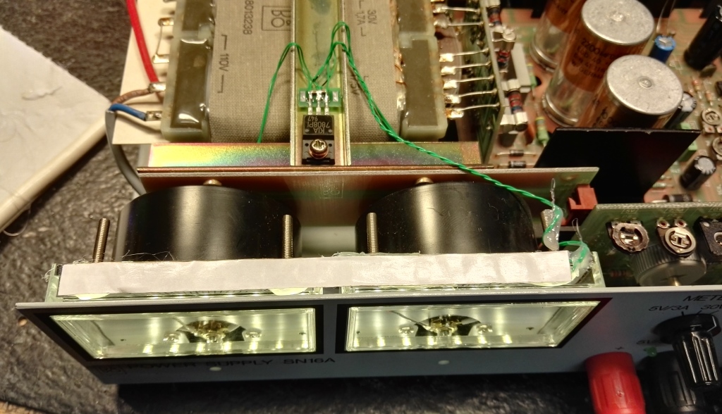
with light from only the bottom, it did not look as perfect as i wanted, so i added one more LED band at the top, as shown here
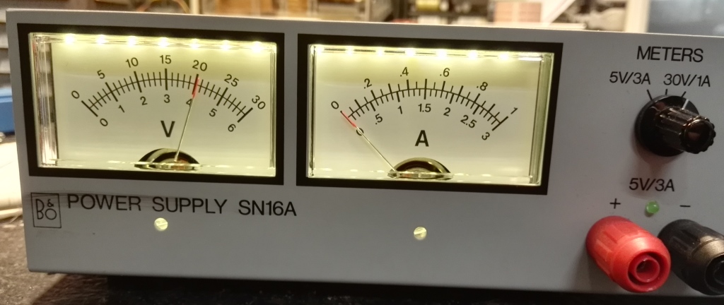
looks much better
Done now back to lab
-----------------------------
Thomas Scherrer OZ2CPU 2018
If you found this page usefull, why not consider donate a bit.. see my contact page please.