 www.webx.dk Start page
 OZ2CPU Radioamateur mainpage
 Homemade electronics Stuff old and new
 USB Keyboard Amiga Joystick for Raspberry Pi Emulator Amibian
www.webx.dk Start page
OZ2CPU Radioamateur mainpage
Homemade electronics Stuff old and new
USB Keyboard Amiga Joystick for Raspberry Pi Emulator Amibian
Foreword:
The Raspberry PI Amiga emulator called UAE4ARM is super cool and fun, however there is NO direct support of joysticks ! ((could have been done using the GPIO like retropie))
A special USB - Joystick adapter must be purchased so normal DB9 connector Commodore Amiga / C64 joysticks can be used.
They are cheap and easy to find, only issue is the WAITING time :-(
You can play all games in single player mode, simply using any type of USB keyboard, arrow keys, and page down as fire.
This gave me an idea, how about we connect the 5 functions of a joystick to the keys of a USB keyboard, since usb keyboards are lying around in the dump, they are free to get
Here is a one hr project, that will make you play all your favorite games allready tonight using your favorite amiga joystick.
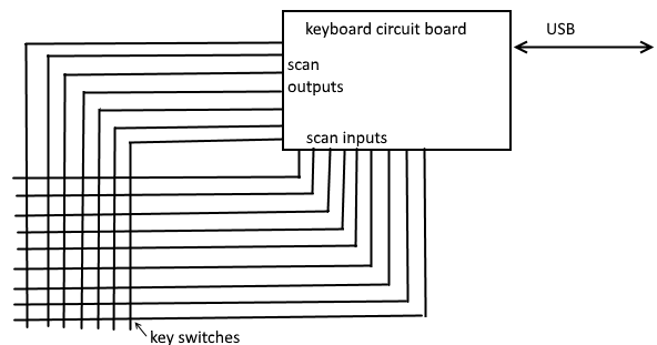
a usb keyboard is made like this, scan outputs, and scan inputs,
each output signal is low for only 10uS, one by one, until all have been low, then it repeat the scan.
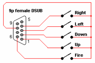
The inside of an Commodore 64 or Amiga Joysticks and actually also many other brands, note the common signal pin 8, is normally used as ground
but as you can see it can also be +5V, then you get active high signals, exactly what we need
only side effect is you will blow up any joysticks with auto-fire electronics inside them, but i dont have any, so no problems here..
There is a female connector on the joystick, so you need a MALE DB9 connector for the joystick-usb-keyboard converter.

So here is the deal, first you test the keyboard is alive, at least the buttons you need to use must work,
open USB keyboard, you see a tiny pcb and conductive tracks on plastic.
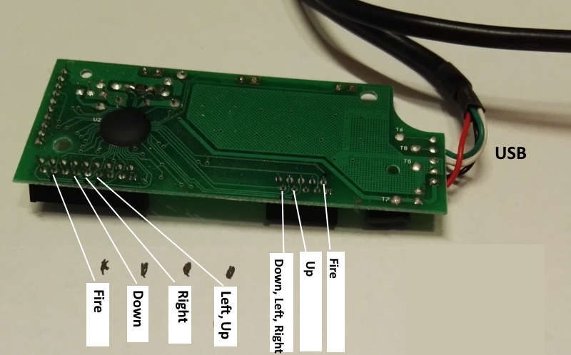
the tracks are easy to follow, good idea to add some tiny dots with permanent marker, so you know for sure where they go.


Always take pictures of all details, so when wires brakes off, you know where to place them again.
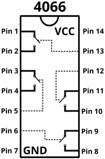
Here is the pinout of a 4066 ic, the control signals are active high, and when high, the relay is closed, now signals from either side are connected together.

Since a keyboard is "scanned" in rows, the signals are not directly compatible with amiga joysticks
there is no access to a one wire signal for each function, so we need to simulate a key press, with a single wire signal from eash joystick functions.
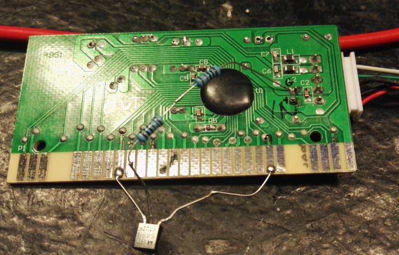
The ic 4066 is four analog switches, think about it as relays with a control line, the control lines are held low (inactive) by 1k resistors as shown here
the ic to the left is the FIRE, so only one switch in that one is used, the 3 other "relays" are just all ground
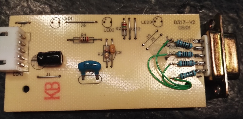
All resistors are 1k. The common pin of the amiga joystick is +5V, this way the 5 signals become active high.

No need to draw schematics, since all brand and types of keyboards are different, but the pcb and connections will look a little bit like this.
at least you will be able to get the basic idea.

Add a ton of heatmelt glue, to keep it all together, after testing, maybe even heatshrink it, so it will look nicer

-----------------------------
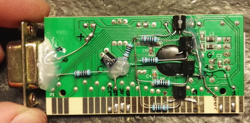
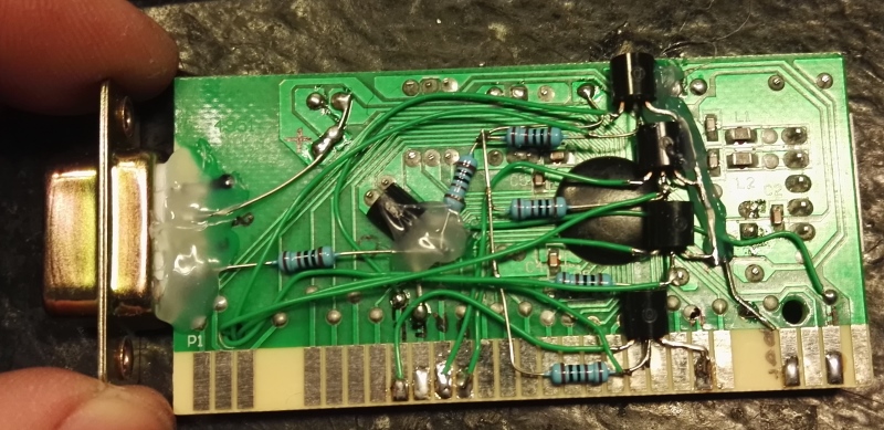
you can use NPN transistors, any small signal type will do, i used BC548, here is first test (all resistors are 1k)
By using transistors you need 5 more brain cells activated, you need to figure out (measure or guess) what is outputs and what is inputs.
On this pcb, all keyboard scan signals to the left are outputs, they go to the Emitter.
all keyboard scan signals to the right are inputs, they go to the collectors.
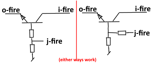
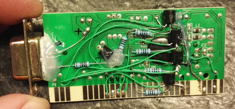
The Fire function is simple, since keyboard scan dont share signals with any other signals we need.
o-fire means keyboard scan out for fire function. i-fire means keyboard scan input fire. j-fire means joystick signal from db9 connector
note the joystick common signal is connected to +5V, this way all joystick input signals become active HIGH.
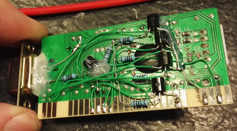
a bit pictures while we work on it
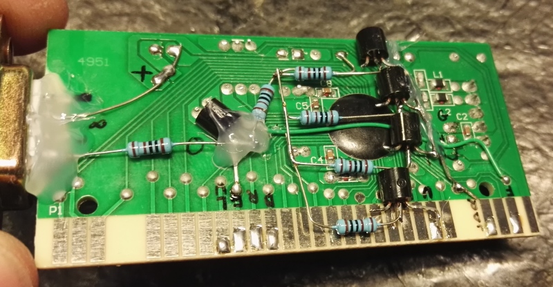
all 5 transistors addes, still a bit wires needed.
top side show the rest of the resistors.
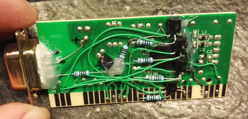
On this keyboard pcb, the output signals Left and Up share the same line
and input lines Left, Down, Right share the same line, no big deal, just connect the transistors correct.
-----------------------------
Thomas Scherrer OZ2CPU 2017
If you found this page usefull, why not consider donate a bit.. see my contact page please.