 www.webx.dk Start page
 OZ2CPU Radioamateur mainpage
 Homemade electronics Stuff old and new
 SP24S050S 24V 50A charger full teardown pictures
 www.webx.dk Start page

 OZ2CPU Radioamateur mainpage

 Homemade electronics Stuff old and new

 SP24S050S 24V 50A charger full teardown pictures
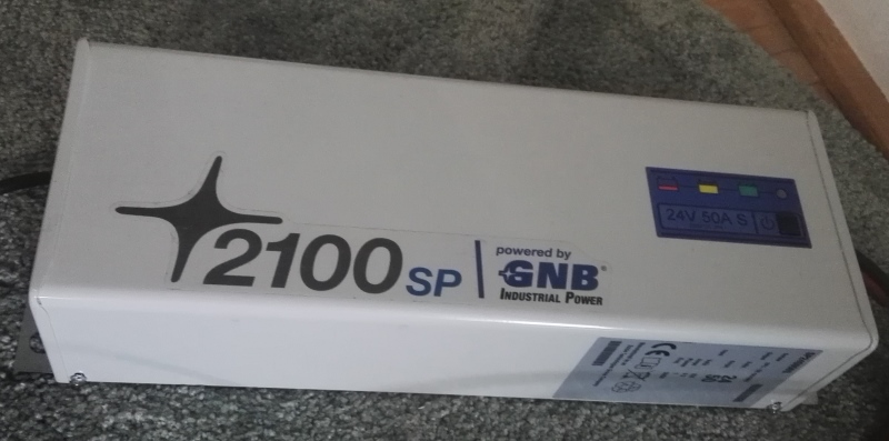
this is a two hand lift job, big and heawy
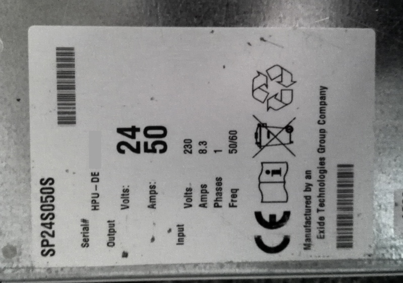
Type name and number and short specs
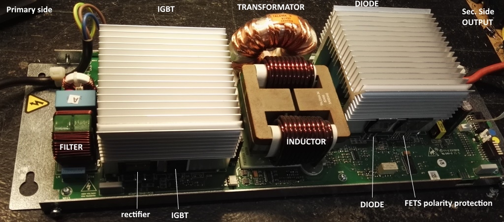
Prim side: filtering done by 3 common mode choke sections, rectifier bridge. 300V pulsing DC (no large value capacitors to hold up the voltage)
Sec side: filtered with one common mode choke, Rectification is made using two double diodes, not active using fets as usually seen on large amp supplies.
The two paralleled FETS on the DC output side, are for battery reverse protection, and it also shuts off all circuits when battery is connected, and mains disconnected.
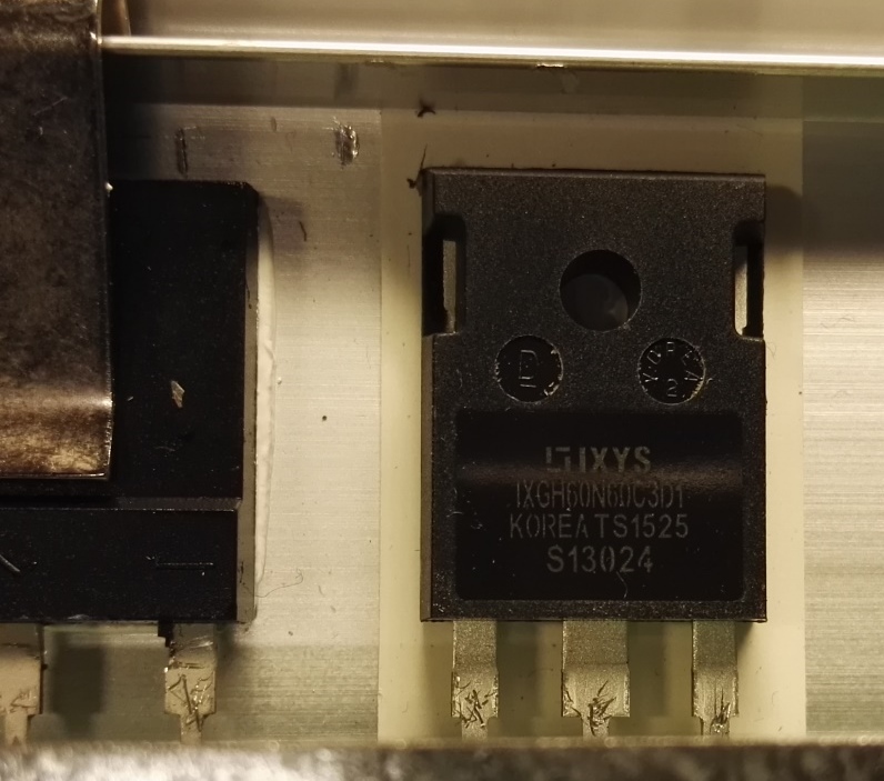
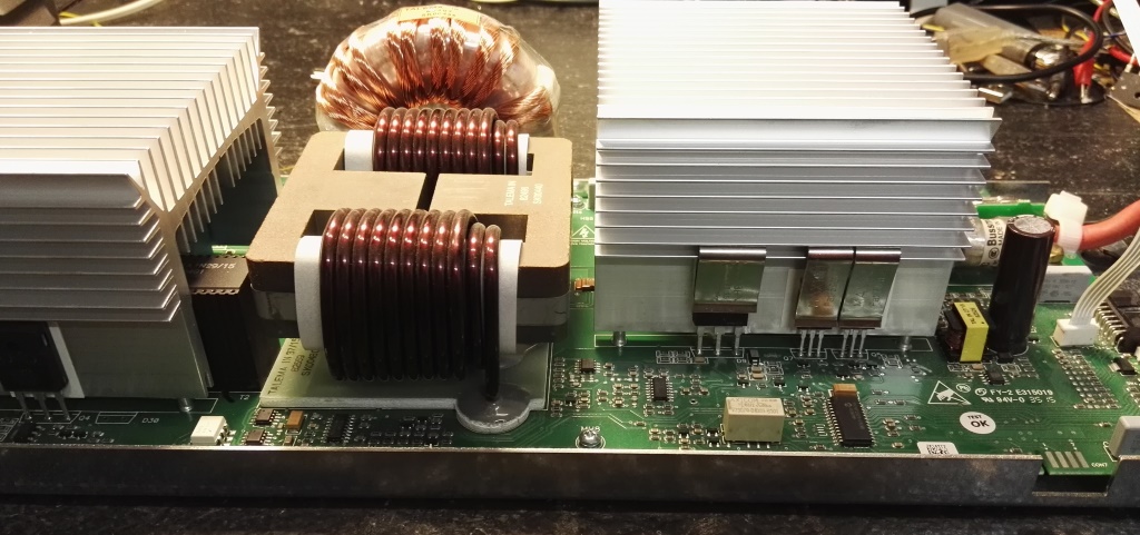
primary side, two large IGBT's
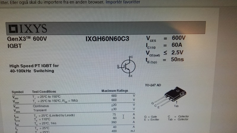
IGBT type IXGH60N60C3 600V 60A
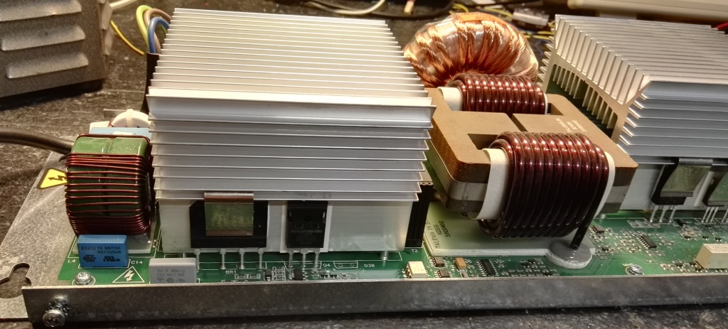
The switch mode topology used is called halve bridge push-pull, this means the "dead" end of the transformator is connected to halve DC supply = 150V
This halve supply if made using voltage divider resistors of high values, and large current capeable capacitors, the four big blue ones under the heatsink, shown later.
the output charge current, follows the mains input voltage curve, since this is a CHARGER not a DC supply,
the avarage charge current is all we care about, and there is plenty of that from this beast.
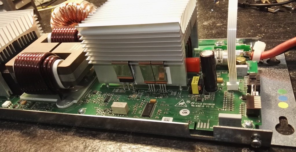
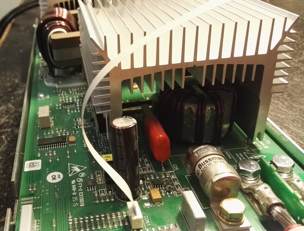
Sec. side fuse is 100A just in case something really bad happens
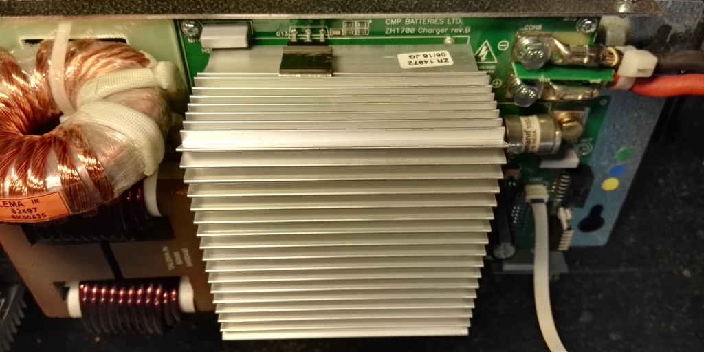

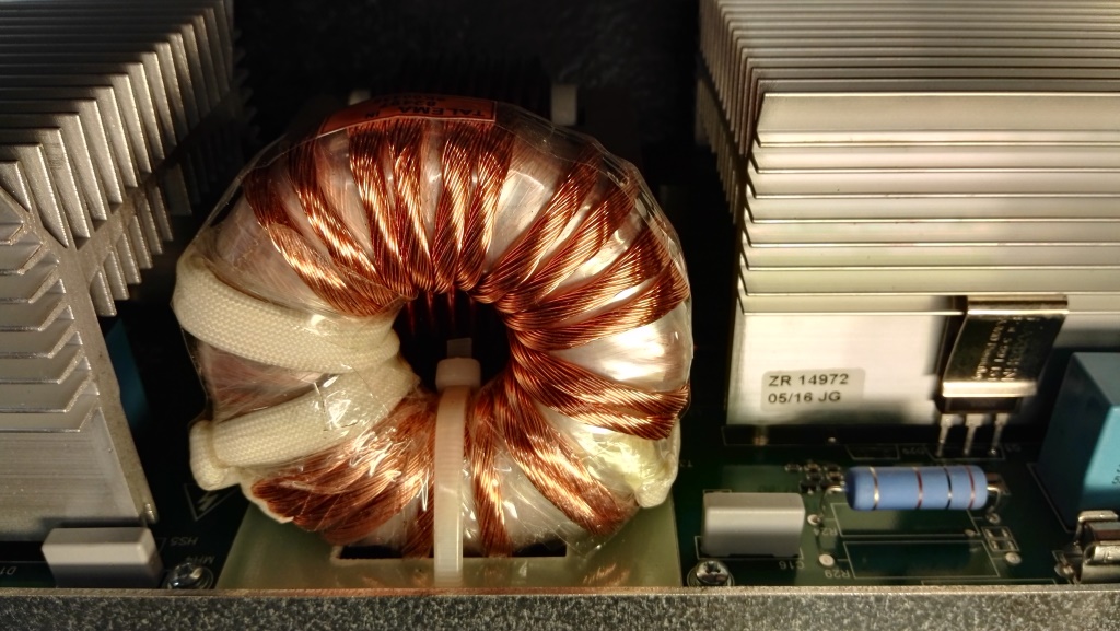
This transformator handle 2100 Watts that is quite amazing, note only 22 turns for the output
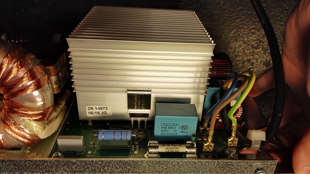
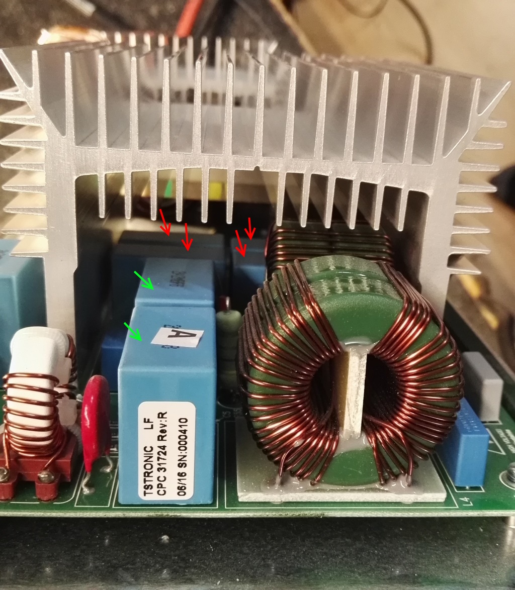
The 4 blue caps under the heatsink are the voltage dividers for transformator center voltage (marked with red)
The two bigger blue caps are used for the two bigger commonmode chokes (marked with green)
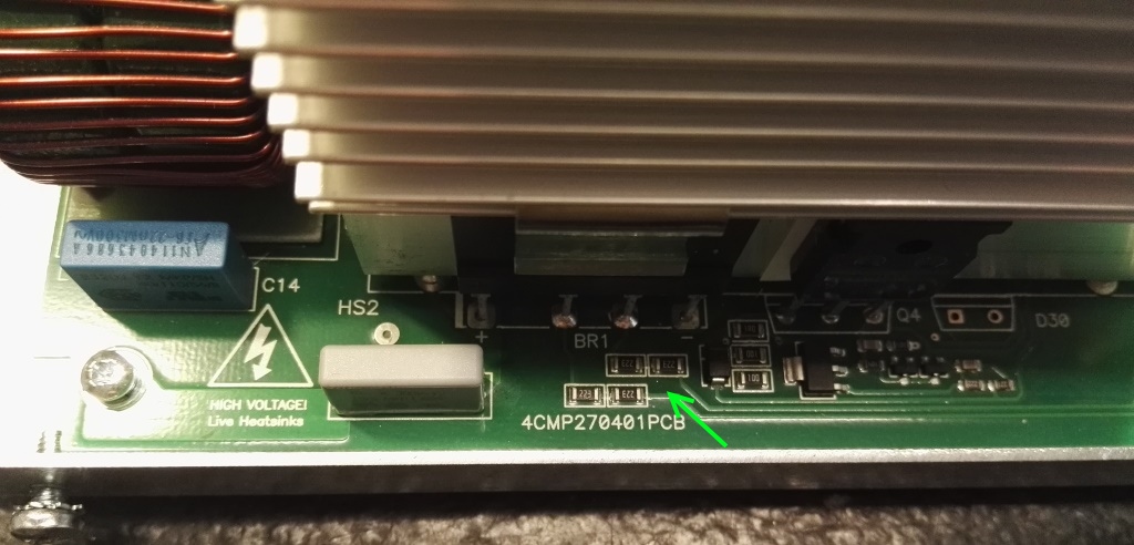
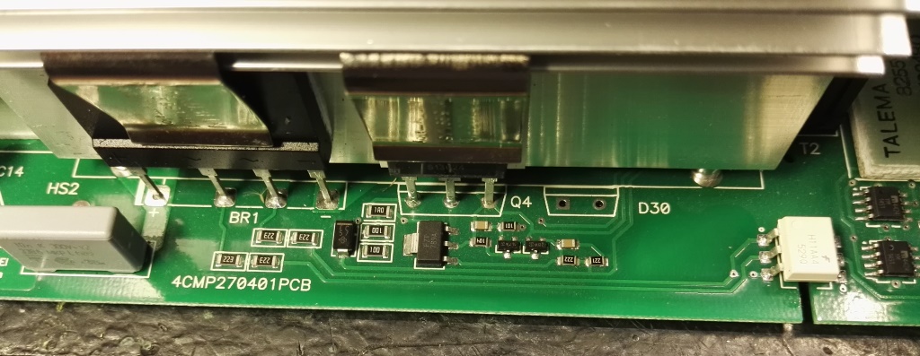
four 22k in series with input mains ac side go to an optocoupler, so the CPU knows there is mains input, and will then boot up the PWM power generator
All logic and the CPU is powered from the battery side, it is sleeping when no AC input is detected.
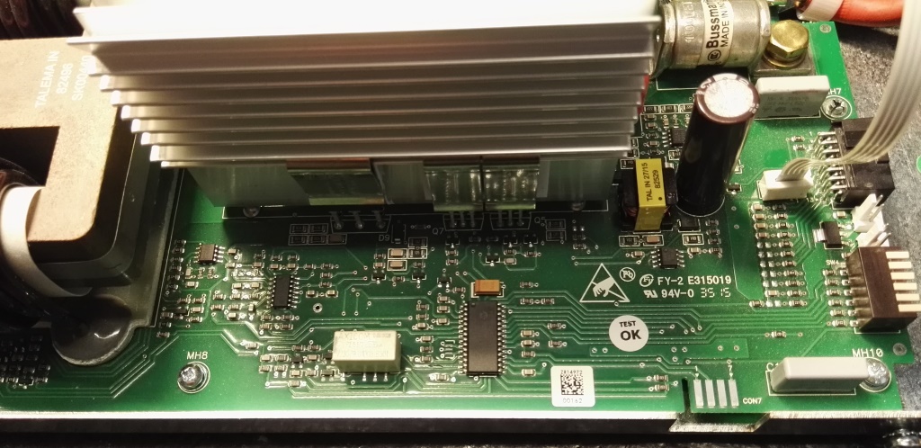
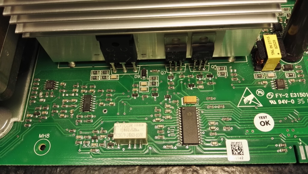
the brain is a PIC16 microcontroller, note also the yellow transformator and the tall capacitor,
They are parts of another tiny switchmode supply for CPU and sec. side logic. using 5V and 12V
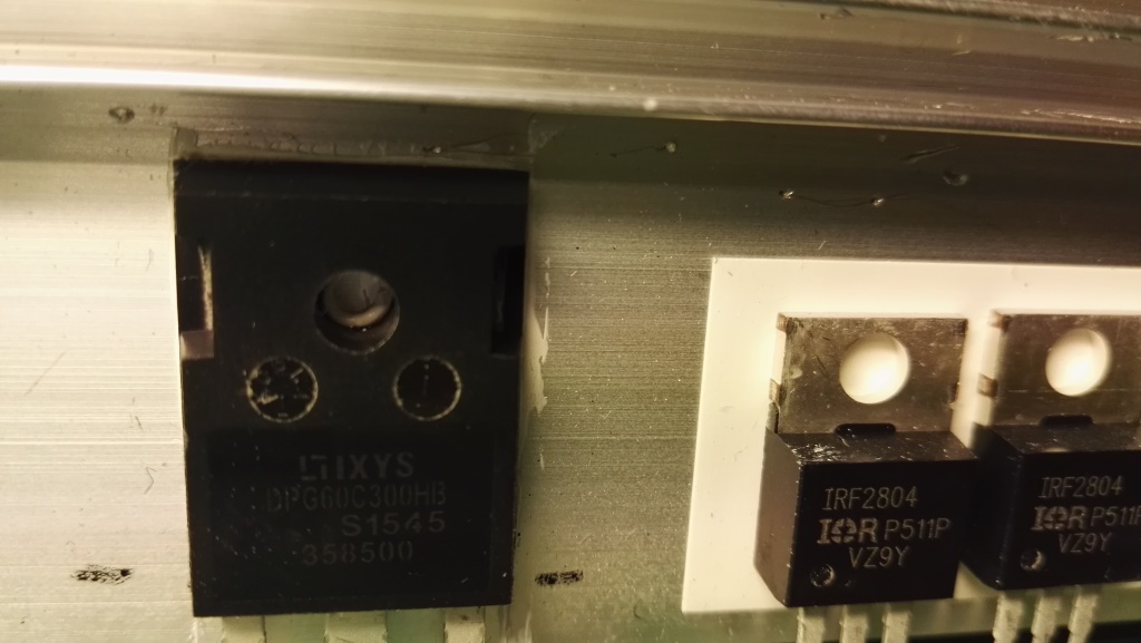
one of the two sec side rectifier diodes, type DPG60C300HB it handle 30A pr diode, (there are two diodes in each package.)
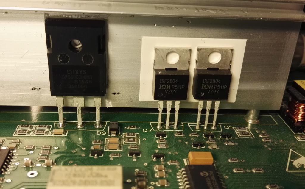
battery polarity and protection, two IRF2804 in parallel (2mOhm 40V 75A each)
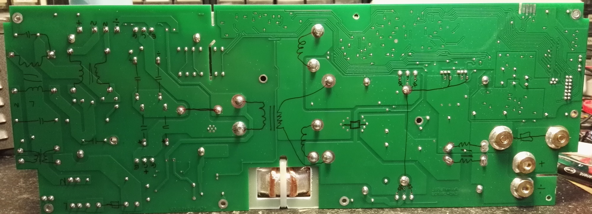
To be able to find my way arround this circuit, I always draw key components on the bottom like this, now it serves as schematic
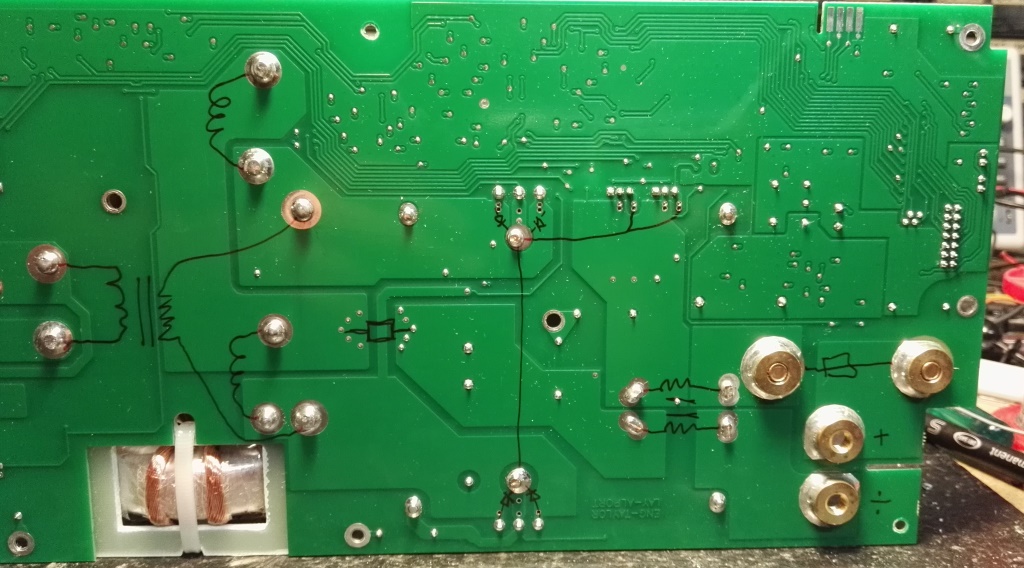
Sec. side only.
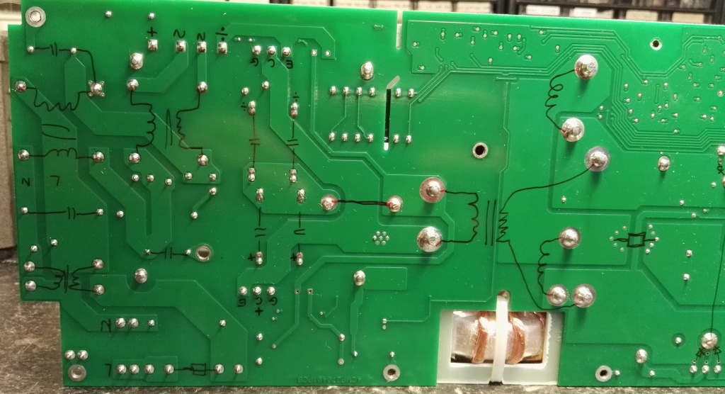
Prim. Side only.
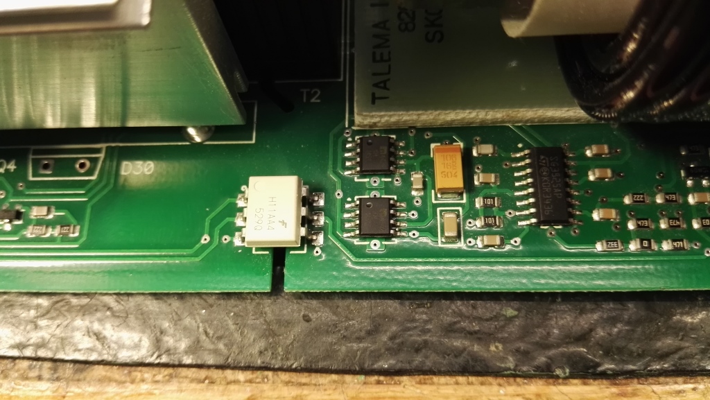
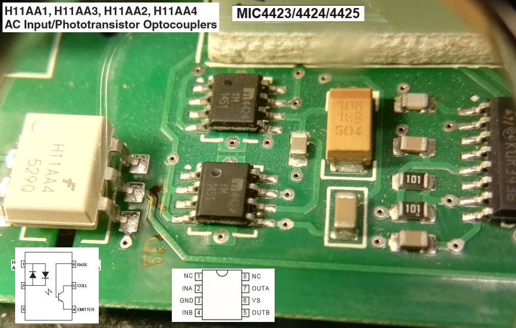
The outputs from the PWM controller go to two FET drivers (however here they drive a trigger transformator located under the heatsink)
this trigger transformator drive the two gates of the two large IGBT's, via some small transistors to make turn off time shorter (JFET)
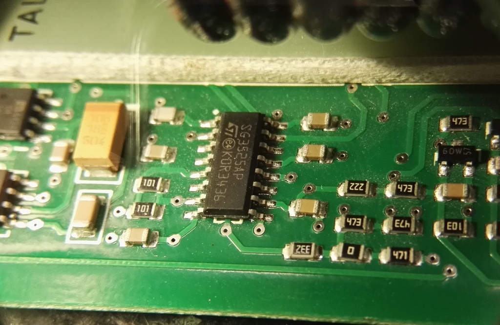
SG3525A is the PWM controller
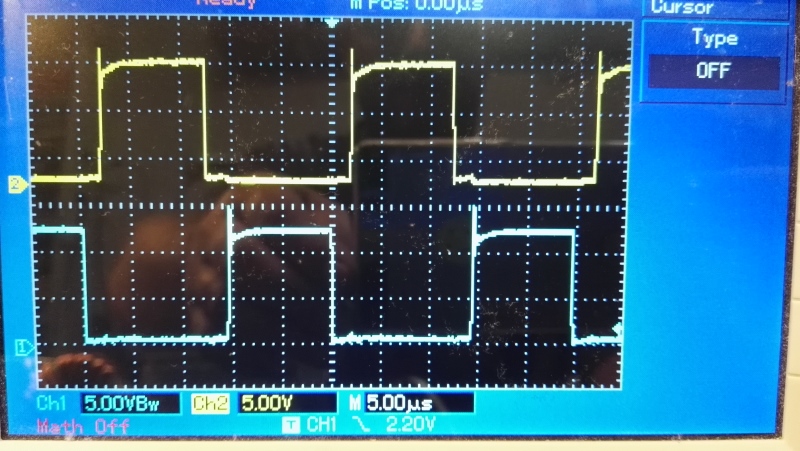
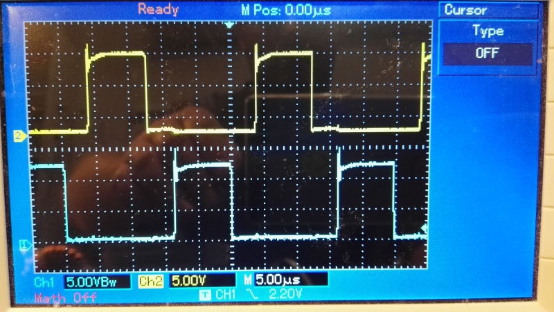
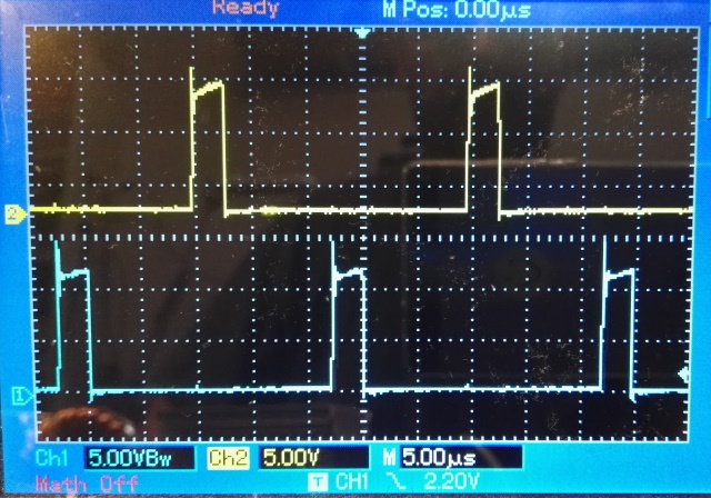
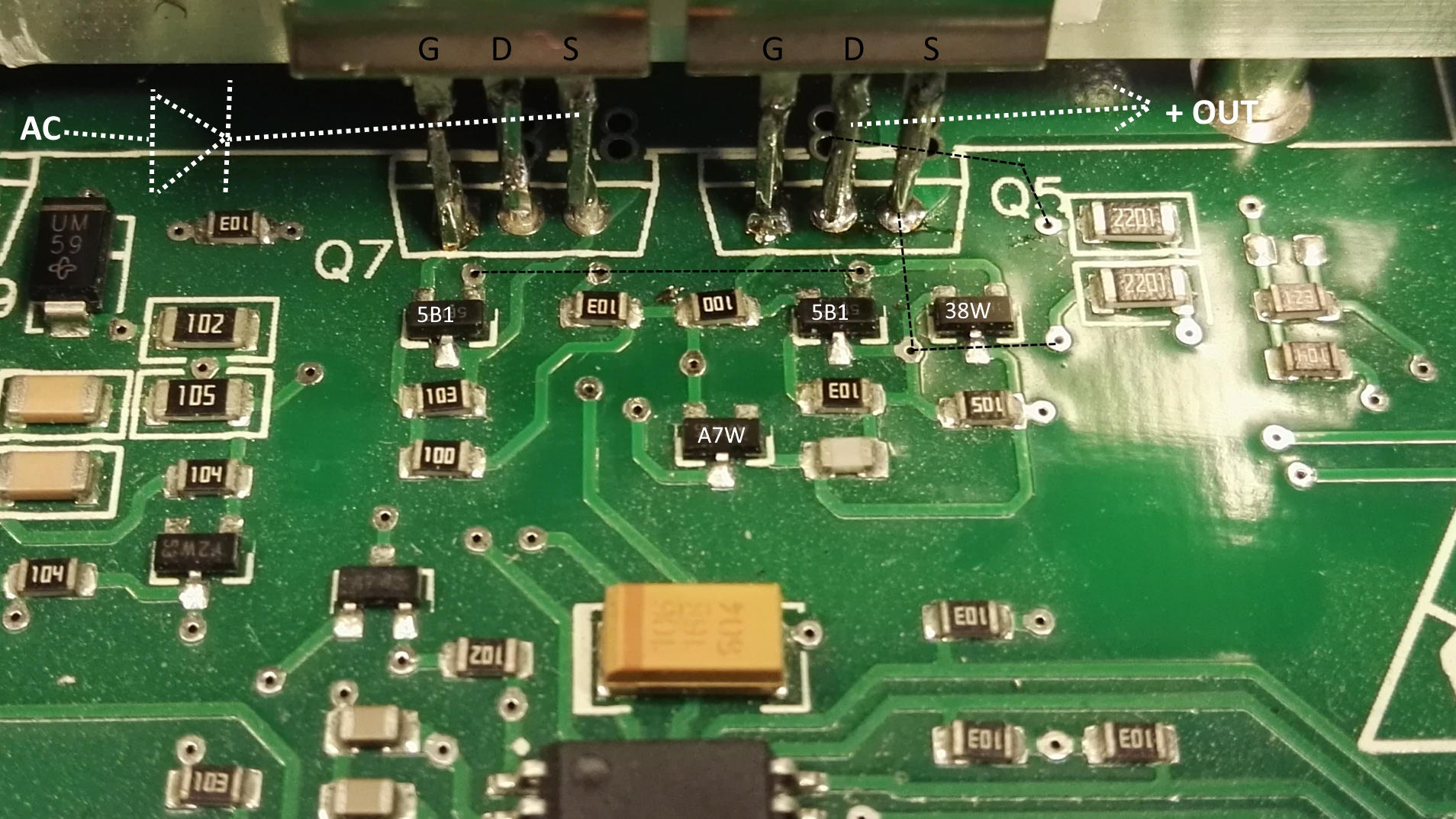
this was the parts that was causing my problem, so i had to draw more datailed info
amazing design, the fets are keept off by using small JFETS to keep the gate to source in ultra low impedance when ment to be off,
and while there is no supply to and parts of the circuits.
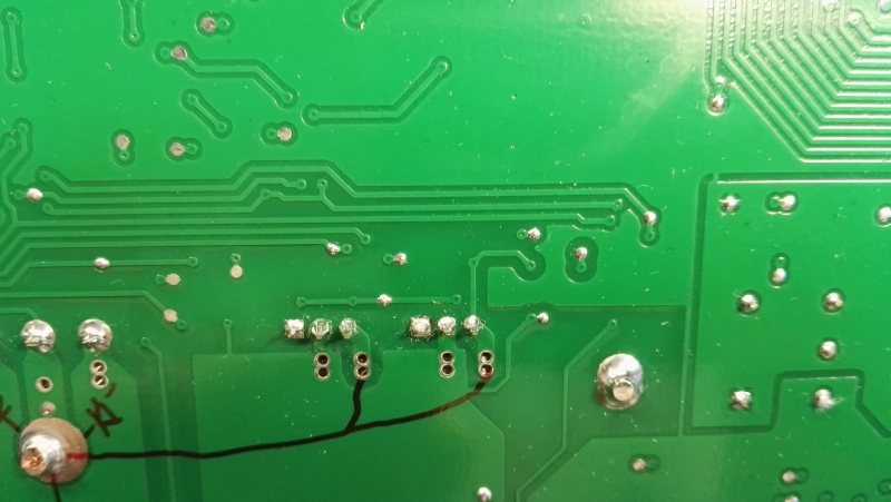
big fat track on top side where the black lines are drawn,
it looks like the normal 35um thickness copper was used in this layout and just two layers.
-----------------------------
Thomas Scherrer OZ2CPU 2018
If you found this page usefull, why not consider donate a bit.. see my contact page please.