 www.webx.dk Start page
 OZ2CPU Radioamateur mainpage
 Homemade electronics Stuff old and new
 Homemade Scope Clock DG7 tube and PIC16F876
 www.webx.dk Start page

 OZ2CPU Radioamateur mainpage

 Homemade electronics Stuff old and new

 Homemade Scope Clock DG7 tube and PIC16F876
(updated: 29. oktober 2005)

Powersupply and CRT deflection and microcontroller test circuit.
I was lucky to purcase two used but working DG7 tubes and a transformator cheap, one from Mullard and one from Phillips.
Other CRT Cathode Ray Tube types can be used, you can even rip one from an old and maybe dead oscilloscope,
then you also get the powersupply and stuff, if you are lucky the deflection amplifiers also work :-)
Then your own home made Scope Clock is soon up and running, good luck.

The test setup seen from top.


Here is the complete scope clock Powersupply schematic and PCB layout. Board with parts.
This powersupply uses an old tube gear transformator, so series resistors was used to make all the different voltages.
Voltages written on the schematic are optimal values for a DG7-32 CRT.. but other tubes can also be used, read below.
Download PSU PCB layout for easy homemade Height = 105mm, Width = 85mm.
Powersupply using special made transformator, using no series resistors:
See schematic the huge capacitors can be changed !
New Powersupply board first test of transformator
New special trafo close up picture.
Trafo in hand see the small size.

The homemade Deflection amplifiers schematic, I used in my scope clock.


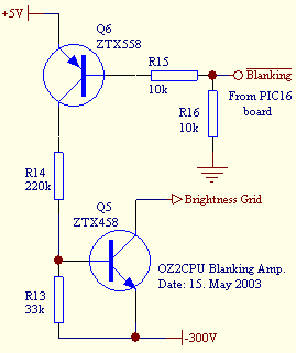
This is the schematic over the blanking circuit, and PCB layout over Deflection and blanking circuit.
Baord with parts and here also
Download Deflection PCB layout for easy homemade Height = 50.8mm, Width = 111.7mm
PIC16F876 board schematic, using ZN508 DAC download and print out (updated May 2003)
PIC16F876 board schematic, using AD7302 DAC download and print out (updated Okt 2005)
See a closeup of my PIC16 demo board this board was easy to change into a scope clock controller.
I use an old ZN508 dual 8 bit parallel input DAC (see glitches), if you want a little bit better picture I suggest you use AD7302 or DAC8229 or AD5332.
If your scope tube is small or maybe a little bit out of focus, you will not notice the glitches.


Now with converter made numbers. . . SET mode is indicated really nice.
Quick time Download of running clock New Latest version has 10th of a sec indicated, looks really great.
Quick time Download of running clock Same but taken with no light in the room.

TUBE CONNECTIONS CRT TYPE DG7-32: (PREFERED TYPE)
1 Cathode -200, and Fillament 6.3V 300mA
2 Brightness Grid. (G1)
3 Connect to pin 1
4 Focus Grid (G3)
5 Not connected
6 Deflection X1
7 Deflection X2
8 Anode +300 (G2)(G4)
9 Deflection Y2
10 Deflection Y1
11 Not connected
12 Fillament 6.3v 300mA


TUBE CONNECTIONS CRT TYPE DG7-6: (usable, but voltages must be adjusted)
1 Cathode -200, and Fillament 6.3V 300mA
2 Deflection Y2
3 Deflection Y1
4 Anode +300 (A2)
5 Deflection X2
6 Deflection X1
7 Focus Grid (A1)
8 Brightness Grid. (G1)
9 Fillament 6.3v 300mA


TUBE CONNECTIONS CRT TYPE 6LO1I CCCP: (WORKS FINE, TOUCH THE SCREEN = MOVES THE PICTURE!!)
1 Cathode -200, and Fillament 6.3V 300mA
2 Connect to pin 1
3 Brightness Grid.
4 Focus Grid
5 Not connected
6 Connect to pin 3
7 Deflection Y2
8 Deflection Y1
9 Anode +300
10 Deflection X2
11 Deflection X1
12 Not connected
13 Not connected
14 Fillament 6.3v 300mA


See little video clip of this clock running: crt-clock-running 214kb
Made in 2003, updated 29. okt 2005. OZ2CPU