 www.webx.dk Start page
 OZ2CPU Radioamateur mainpage
 Homemade electronics Stuff old and new
 Robot 100kg the jeep, main selector page
 Robot 100kg the jeep, ELECTRONICS
www.webx.dk Start page
OZ2CPU Radioamateur mainpage
Homemade electronics Stuff old and new
Robot 100kg the jeep, main selector page
Robot 100kg the jeep, ELECTRONICS
this page will cover all sorts of electronics not allready explained in the other sections of the pages

electronics-block-diagram.png


CONNECTOR PINOUTS OSD:
DB9 MALE, ORANGE COLOR
1 9V input (power from the cam remote ptz controller ??)
2 Temperature 1, input 1V max LM60 (T2 is internal)
3 BEC volt, RSSI input
4 V1 battery voltage 24V (from 24 to 9V converter)
5 Current Measure input (from sense resistor gain amplifier)
6 Gnd input
7 Gnd
8 R/C servo signal input for video selector
9 R/C servo signal input for OSD


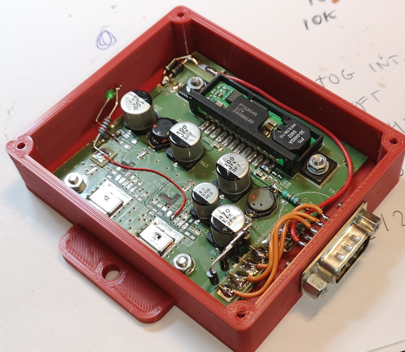
electronics_smps_arduino.jpg Powersupply for all Arduino units, based on some old boards i designed many years ago PT6304R 16-38V input, 12V out 3A
I like this module a lot, for its wide input range, and wide output voltage trim, both up and down, very usefull, just too bad it is obsolete.
CONNECTOR PINOUTS :
DB9 MALE, RED COLOR
1 24V input (power from the powerpanel)
2 nc
3 9V out via 1N4001
4 9V out via 1N4001
5 9V out via 1N4001
6 Gnd input
7 Gnd
8 Gnd
9 9V out via 1N4001


CONNECTOR PINOUTS :
DB15 MALE, BLUE COLOR
1 9V input, (via 1R resistor and 15V zener)
2 nc
3 TX1 out, to motor power drive optocoupler 9600 baud
4 +5V via resistor, to motor power drive optocoupler
5 RX2 input 9600 baud, from tacho counter (100mS updates all synced to this)
6 RX3 input 9600 baud, from setpoint unit
7 nc
8 nc
9 GND
10 GND
11 GND
12 GND
13 GND
14 GND
15 GND

CONNECTOR PINOUTS :
DB9 MALE, YELLOW COLOR
1 9V input (arduino power)
2 analog A
3 analog B (auto detect if connected joystick for drive test)
4 ppm input
5 serial 9600 out to PID
6 Gnd power
7 Gnd signals
8 nc
9 5V out for analog joystick
END of this section, NOT COMPLEETE YET