
 www.webx.dk Start page

 OZ2CPU Radioamateur mainpage
 Homemade electronics Stuff old and new
 Robot 100kg the jeep, main selector page
 Robot 100kg the jeep, Motor Brake Remove Modifications, Tacho

mot_20180913_133550.jpg

mot_20180913_133554.jpg

mot_20180917_103357.jpg

mot_20180917_103428.jpg

mot_20180917_103438.jpg

mot_20180917_103447.jpg
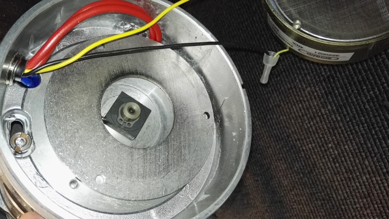
mot_20180917_103458.jpg
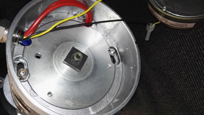
mot_20180917_103505.jpg

mot_20181001_121334.jpg
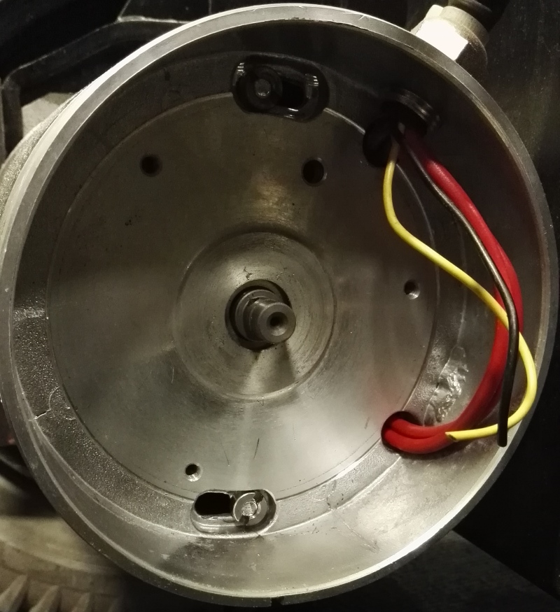
mot_20181227_171356.jpg

mot_20181227_171402.jpg
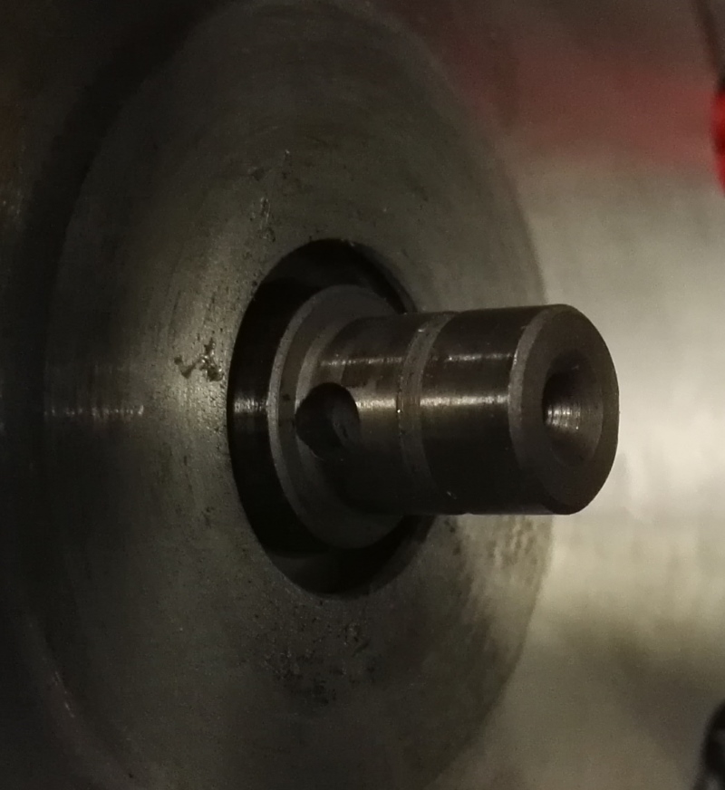
mot_20181227_171411.jpg
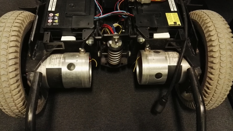
mot_20181227_172832.jpg

mot_20181227_172834.jpg
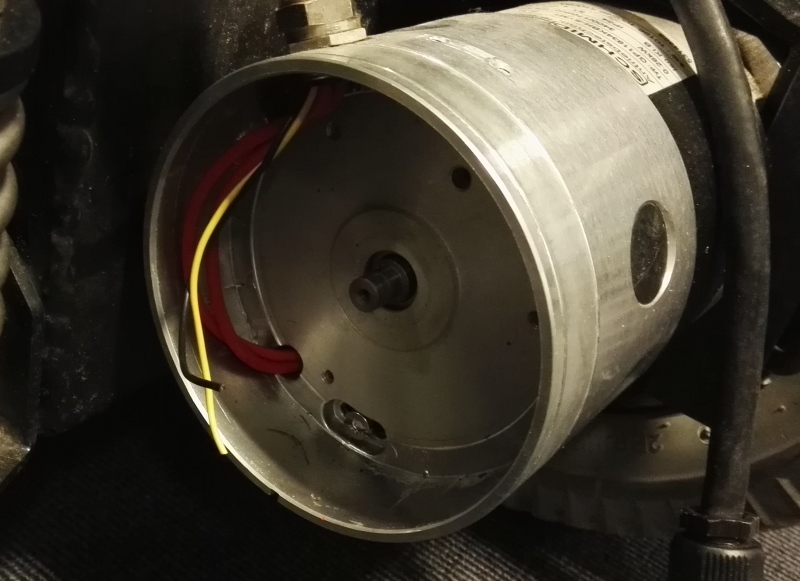
mot_20181227_172837.jpg

mot_20181227_172841.jpg

mot_20181227_172847.jpg

mot_20181227_172849.jpg

mot_measurements-tacho-design.jpg - notes from back side of motor, now i can design the tacho parts

mot_tacho_center_fusion_design.jpg - to be glued to the motor shaft

mot_tacho_wheel_fusion_design.jpg - the tacho wheel is easy to unscrew and replace, maybe i laser cut a hires one later
so far this 50 pulse 3D printed one is good enought for first tests.
motor is geared 20:1 so i think I get enought pulses to be able to drive really nice and slow with good resolution

mot_tacho_parts_assembled_20181229_231113.jpg - 3D printing came out quite good

mot_tacho_parts_assembled_20181229_231046.jpg
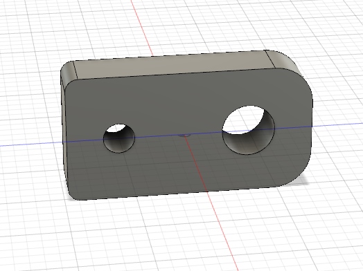
mot_tacho_ir_detector_holder_fusion.jpg

mot_tacho_sensors_ready_20181230_143042.jpg

mot_tacho_sensors_details_20181230_141402.jpg

mot_tacho_hub_and_sensor_20181230_152345.jpg
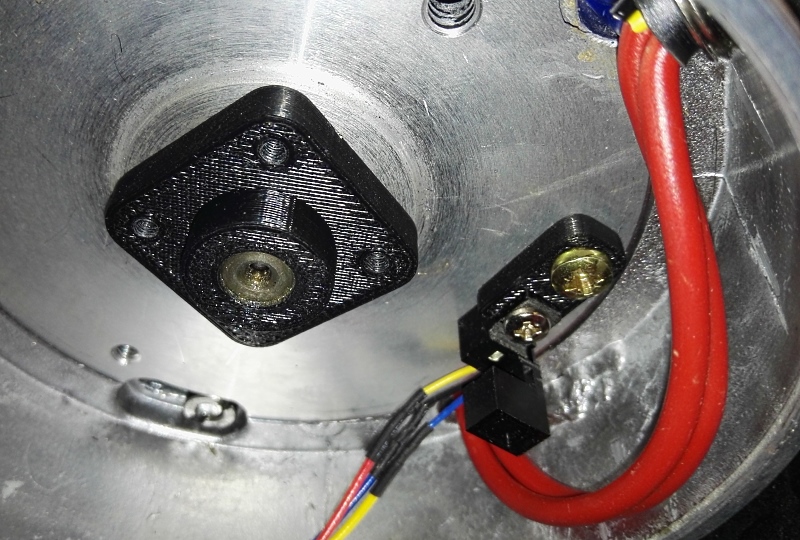
mot_tacho_hub_and_sensor_20181230_152352.jpg

mot_tacho_mounted_20181230_162101.jpg

mot_tacho_sensor_20181230_162109.jpg
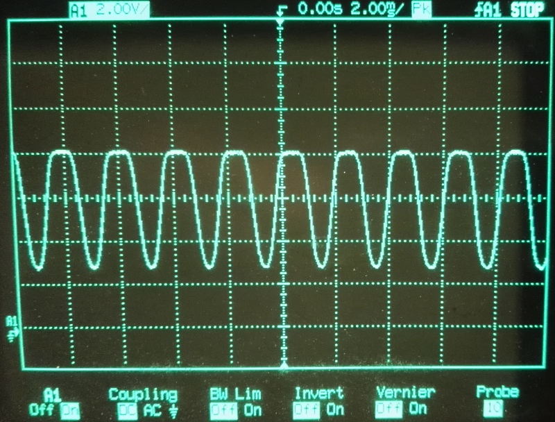
mot_tacho_scope_20181230_162410.jpg
50 pulses pr motor rev, motor to wheel ratio 20:1, wheel radius 165mm,
1000 pulses pr wheel rev, this means i got about 1mm robot movement pr pulse,
so that is maybe a bit too much (can we have too much resolution)
IR LED needed 16mA corrent 500ohm to 8V, and the detector 10k pull up to 8V, else there was weak signal,
now I got about 5V signal, perfect for my next idea..

mot_tacho_schematic_150153.jpg
Motor tacho optocoupler schematic, with hysteresis, the final version
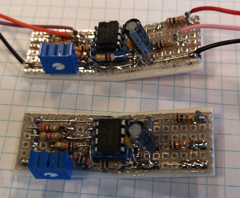
mot_tacho_pcb_132622.jpg
the pcb is bend to make it fit inside the round motor flange

mot_tacho_pcb_150203.jpg
The assembled pcb
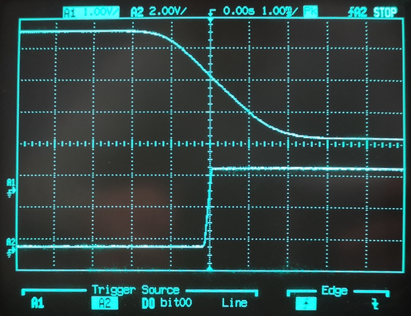
mot_tacho_trig-no-hyst-150351.jpg
Curve without the hysteresis resistor

mot_tacho_curve-hyst-150216.jpg
Curve with hysteresis , this way it will not generate pulses when standing still
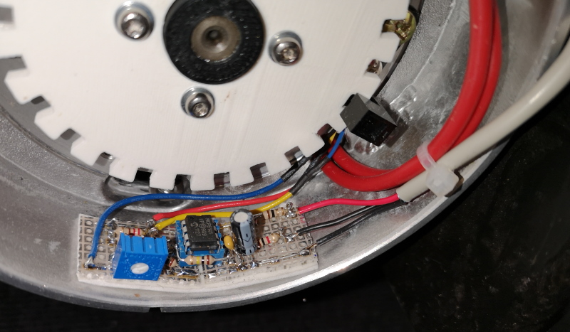
mot-tacho-monteret_164403.jpg
mounted inside the motor.
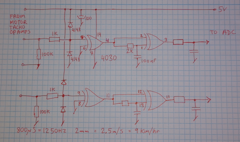
mot-tacho-pulse-to-dc_205448.jpg
The first version tacho pulse to DC voltage converter
this works fine at halve to full speed, but at zero to slow speed, the dc voltage jumps alot, and if I add a big smooth capacitor,
then the regulation becomes very slow and jerky, not the most perfect way to do it
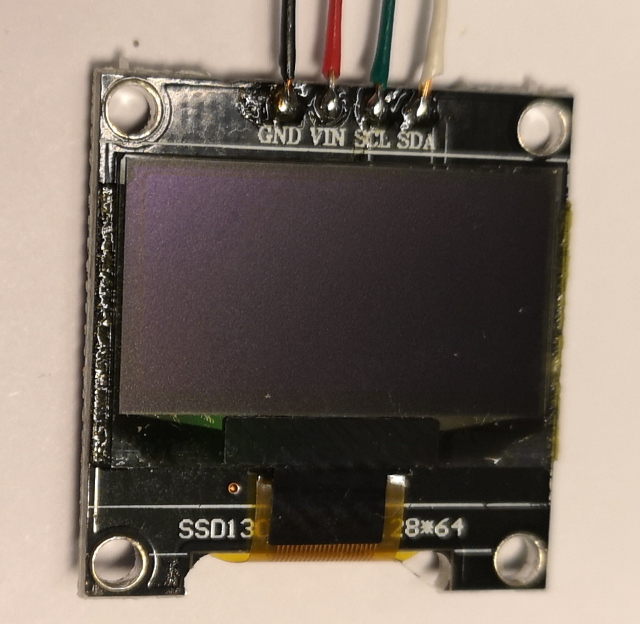
mot_tacho_173523.jpg
I just love those small cheap OLED displays, nice and easy to add a little realtime debug screen to anything
this one is called SSD1306 128x64 pixels.

mot_tacho_205018.jpg
Made a 3D printed case for arduino and OLED

mot_tacho_205149.jpg
The software to read the two tacho signals, a 10kHz interrupt routine handle it.
got a little bit of help with the timer configure thanks again DZL :-)

mot_tacho_205126.jpg
Looks like there is plenty of time to send the result via 9600 Baud, and handle the display
100mS pr reading (both channels) so I expect this will be fine to create a stable distance locked loop
NOTE to my self : Arduino pins
8 = Right tacho pulse input
9 = Left tacho pulse input
10 = sample done, 100mS pulses out for triggering if needed
9600 Baud, data format is clear ascii readable : L123R456
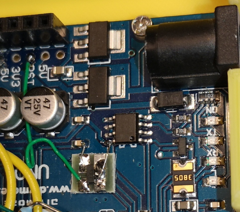
mot_tacho_arduino-reset.jpg The nature of voltage rise time from the switchmode,
made some of those cheap arduino clones confused, so they refused to startup
adding a cpu reset chip like shown here, solved this problem, so i added this to all my arduino boards, no matter what brand
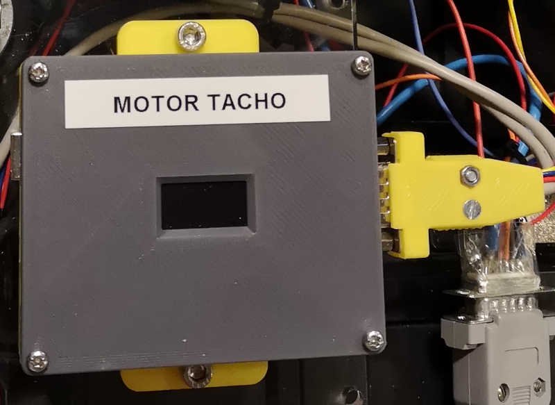
mot_tacho_sensor_in_new_case_yellow.jpg

mot_tacho_assembled_inside.jpg

mot_tacho_inside-closeup.jpg

mot_tacho_installed-and-working.jpg
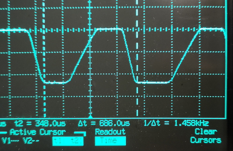
mot_20210619_214131 24V 25teeth 1500Hz, this is max speed
CONNECTOR PINOUTS :
DB9 MALE,YELLOW COLOR
1 9V input (ardu power from smps)
2 5V for tacho amplifier board
3 5V for tacho amplifier board
4 Pulse input Left
5 Pulse input Right
6 Gnd input
7 Gnd tacho amp boards
8 Gnd serial
9 Serial output 9600 Baud
END of this section, mission compleete, Feb 2020 OZ2CPU
----------------------
The saga continues, due to PID problems, both motor encoders are now upgraded to Quadrature !
NEW updated pinouts June 2021
CONNECTOR PINOUTS :
DB9 MALE,YELLOW COLOR
1 9V input (ardu power from smps)
2 Pulse input Right A (Arduino io 2)
3 Pulse input Right B (Arduino io 3)
4 Pulse input Left A (Arduino io 4)
5 Pulse input Left B (Arduino io 5)
6 5V for detectors
7 Gnd
8 Gnd serial
9 Serial output 9600 Baud
new detector:
OPTEK TECHNOLOGY OPB461T11 Optical Switch, OPB460 Series, Photologic®, 0.25 mm, Open Collector, 4.5 V to 16 V
Farnell code : 1678598

The new sensor come with build in hysteresis, so that is nice, but not in any compatible mounting option as i needed,
so a little bit cutting is needed.
Diode forward 1.4V @ 20mA so i can connect two in series = 2.8V and 110 ohm to 5V
collector pull up 1k and 10 nF to gnd for bandwidth limit to 16kHz ( i sample at 20kHz but handle counts upto 4kHz

new detector in 3D printed holder.
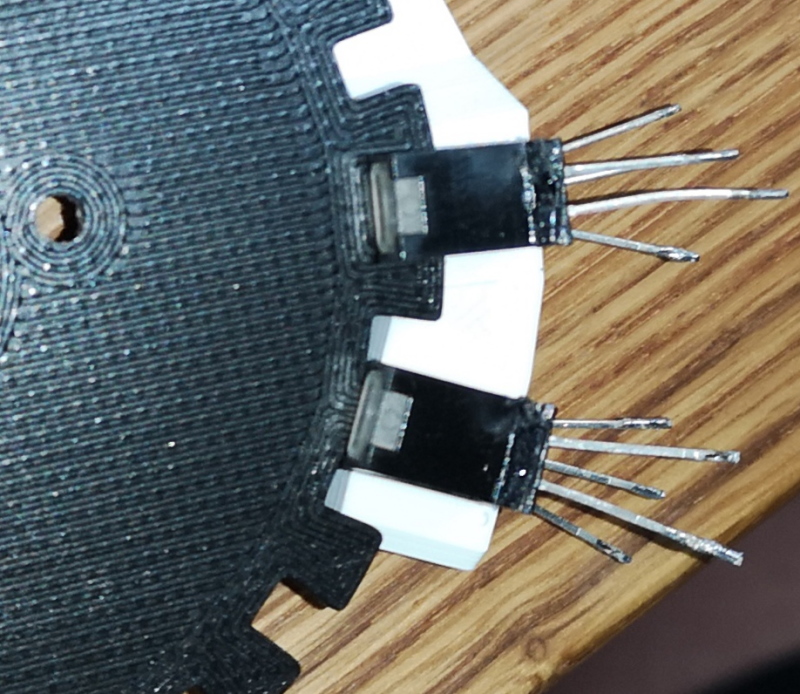
new sensors in carefull quadrature phasing, note one is in centre of tap, and one is centre of hole.

inside

close up of new upgraded module">

the new dual Quadrature unit, handle 4.1kHz om both Left and Right channels at the SAME time,
sample speed 20kHz, since a single waveform is 4 transistions it is quite impressivle to handle both
at 4.1khz with 20khz sample interval.
the result is send 10 times pr sec, in 9600 Baud,
L123R456 (for positive)
L000R00 (for zero)
l123r456 (for negative values)
this way the PID unit will have very little software needed to handle the incomming values

sensor wiring

sensor wiring done, i prefer to reuse old USB cables, thin shilded multicable and free :-)
END OF THIS UNIT (20/6 2021)